There are a great number of custom made keyboards out there. I’m interested in many of them, but I have a soft spot for split keyboards. Some of those keyboards take a sculpted form: fitting the contours of your hand, allowing for less hand movement and supposedly greater comfort.
I used to have a joystick: the Thrustmaster HOTAS Warthog. It’s a replica of the units found in the U.S. Air Force A-10C attack aircraft. I didn’t use it quite as often as I wanted, but it made for a very fine input device.
The Thrustmaster HOTAS Warthog, an excellent joystick and thruster for use in flight and space simulators.
This joystick features a large number of inputs, from sliding buttons, push buttons and toggle switches, to analog shoulder buttons and potentiometers.
It got me thinking: What if I could make a keyboard that you grip like a joystick, but operate like a normal keyboard?
Design goals
There are a few goals that I’d like to accomplish with this design. Some of those are based on assumptions, and it’s a good idea to write those down so I can revisit them later on.
A vertical keyboard
The main goal is to make a vertical keyboard. When people walk, their hands are parallel to their bodies. When you sit in front of your computer and extend to reach your keyboard, you’ll need to rotate your hands in order to type. The assumption is that a parallel hand orientation is more natural and will provide for a more ergonomical position.
A split keyboard
In line with the natural hand position, extending your arms in front of you parallel to the way you look is more natural than bending your arms inwards. Having the keyboard be split will allow for a more ergonomical arm position.
A unique keyboard
I’m interested in making something that hasn’t been done before. It’s probable that this idea won’t work, but at least I’ll have explored a part of the design space allowed by the idea.
Sculpted keyboards
Before I started with my own design, I searched for various sculpted keyboards. Sculpted keyboards don’t necessarily follow the form of a joystick. They do provide for good examples: they reduce the distance from the natural finger position to each key, which will be necessary when tilting the keyboard vertically.
One of the more popular sculpted keyboards is the Dactyl, a 3D-printable handwired keyboard that’s parameterized for personal adjustment. It has a bowl-shaped plate, placing each key along both a horizonal and a vertical curve.
Another version of the Dactyl is the Dactyl Manuform. It changes the thumb cluster to the shape of the Manuform keyboard, retaining the split (see also the Manuform post on Geekhack). One of the ideas in making the Manuform was for all thumb cluster keys to actually be ergonomically reachable by the thumb.
Tom Short made a few preset variations of the Dactyl Manuform design, one of which has an almost vertical tent. With some imagination, this inches closer to a joystick shape, but we’re not quite there yet.
Pseudoku has been quite busy with his Warped keyboard, a keyboard shaped exactly to the shape of his hands. It’s truly unlike anything else out there. Perhaps, if tilted vertically, this could get to where I want to go with my design!
Clay is a relatively cheap and easy to work with medium to get a better idea of shapes and dimensions. I set out to create a clay model that would roughly convey the design direction.
It turns out 500g of clay isn’t a lot, so I ran out before completing my model. Still, it allowed me to get a general idea of what I’d like the end product to look like.
Top view of the clay model.
Don’t pay too much attention to the key positions for now: it’s quite messy and will definitely need a lot of attention tweaking each key position to be comfortable to press.
Side view of the clay model.
3D Modelling
With the clay model mode, I then started on the case. The case has various aspects:
The plate, containing most of the keyboard’s keys;
A thumb cluster, containing the keys that can be hit by the thumb;
A hand contour, shaping most of the case and allowing my hand to rest comfortable on and against the keyboard;
Fasteners, a way to detach the key plate from the rest of the case to allow for the assembly of electronics;
Connectors, allowing for a way to connect the keyboard to the other half and to the computer or other host.
Some of these aspects were new to me, especially designing a natural shape within a CAD program. I started with the main case itself, containing both the keyplate and the hand contour.
Plate and hand contour
Not knowing about natural modelling, I first started a design, working from the bottom of the case to the top.
A first work in progress on the case.
This way of working allows some control over the position of each column, but it isn’t easy to work with. Adding a natural hand contour by doing just this wasn’t working out.
The next attempt was to sweep a sketch profile along the edge of the case, instead of meddling around with fillets and chamfers. This provides more control, but does this mostly in only one axis: Adding more complex depth to the contour requires other tools.
Sweeping a sketch profile across the edge of the case provides some amount of contour. This is a technical demo, my hand thankfully isn’t shaped like this.
Not quite getting there with the sweep tool, I followed a tip from various members of the Reddit r/mechanicalkeyboards community on Discord. They told me that the Form tool was a tool meant for this kind of use case. I then started by creating the basic shape of the keyboard, adding contours later.
A basic shape of the keyboard.
Adding contours using the Form tool proved quite a task, I should definitely follow more tutorials on this before I’ll be able to get a consistent result.
Adding a Form to the keyboard.
Plate
At this point, I decided it would probably be wise to determine where to place each key first, since that will also determine the contour shapes and placement of the thumb cluster.
I split up the keyboard in components: The keyboard itself, which was an assembly of the plate and a case. The plate then was assembled with multiple key columns.
A single column of keys, positioned on its side.
Trying to get a quick prototype together, I first made a single key column. It took two iterations to get a good idea of how close each key could be to eachother.
Printing multiple variants to get a feel for keycap clearances.
Then, eyeballing the dimensions, I modelled the plate containing the columns, each at varying angles based on the length of my fingers.
A recent version of the plate.
I printed the plate using my 3D printer, a Creality3D Ender 3. It was printed using the Simplify3D slicer, using the default “Fast” settings for PLA plastic. This means a layer height of 0.3mm. I adjusted the temperature to 205°C in accordance with my filament’s guidelines.
The printed first version of the plate.
I learned quite a few things from this first print:
The home row and outer rows aren’t accessible enough, requiring too much of a stretch to press the keys.
The force required to press the keys is too high: I’ll need to use other switches or alter them with other springs.
I altered the angles of each column, but that isn’t enough: I also need to adjust the depth and horizontal offset of each column, placing the keys for the index and pink fingers higher for example.
There is too much space needed in the case near the innermost (most angled) key.
The transitions between each column are too small, causing some print issues.
I doubt there’s enough space to add a thumb cluster at all. The clay model only contained four columns, but my 3D printed prototype contains six. The bottom column isn’t a problem because I can make the hand rest higher, but the top column is a problem since it occupies the same space as where the thumb buttons would be.
All in all, most adjustments seem to be easy fixes. The thumb cluster will be a problem though, and it might make the entire idea unfeasible. I’ll have to see what to do about that.
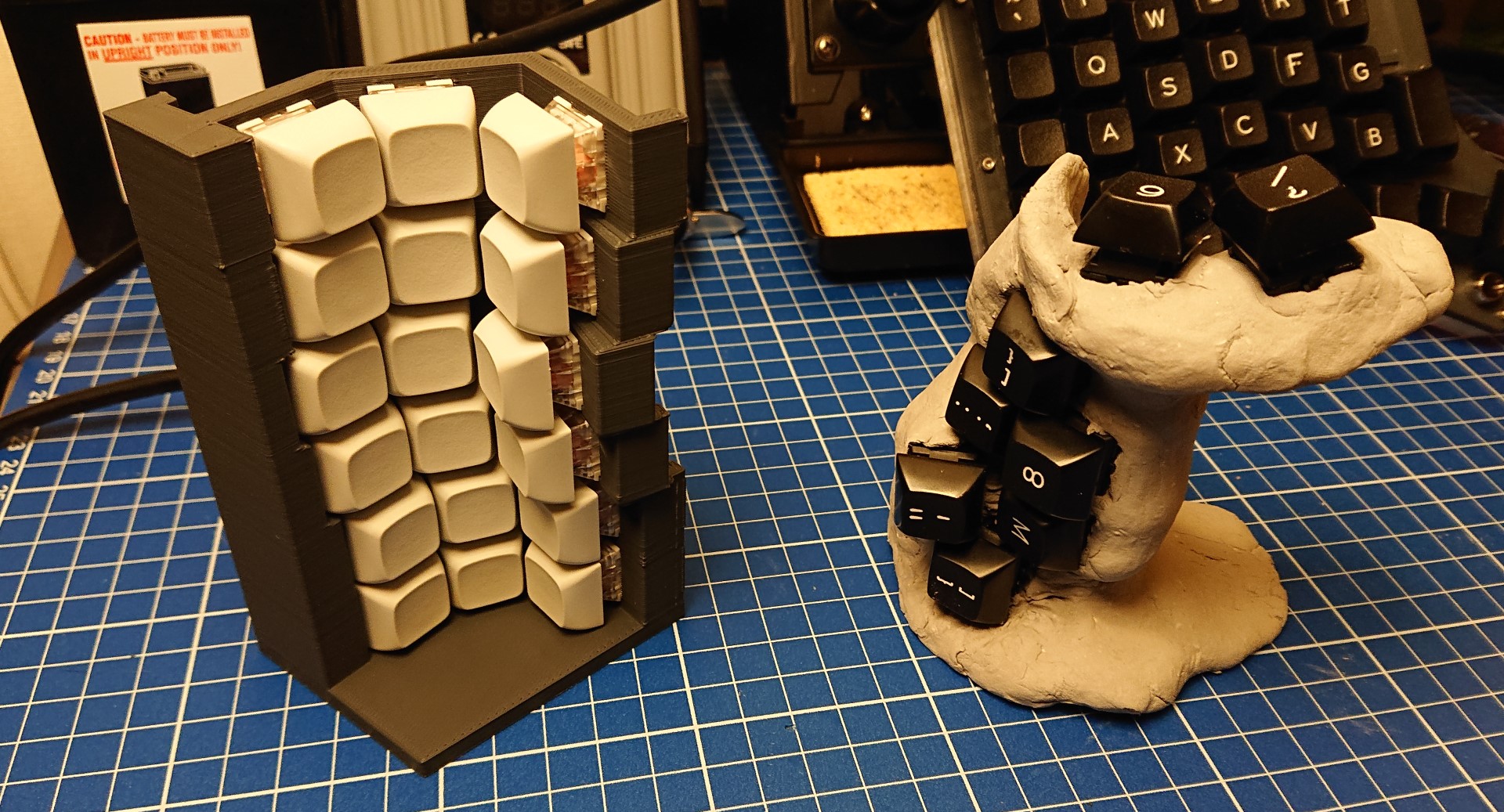
The printed prototype next to the initial clay model.
A second attempt
Taking the lessons learned from the second iteration, I made a new column. I rotated the notches in each switch cutout to the vertical side, allowing more space between columns. I also added filleted edges, providing more space within the case and a smoother edge near where my fingers would curl around the keyboard.
The second version of a column.
I also placed more emphasis on sketch relationships and parametric design, making for quite a clean sketch.
Sketch of the column, showing its side profile.
I printed a single column to get a feel for the changes I made so far, and it’s looking good!
Comparing the side profile of the first version with the second.
Next steps
I spent quite a bit of time this weekend getting the first versions to be where they are. Next up:
Figure out where the thumb cluster should be positioned. This makes or breaks the project.
Decide on column and key positions: What should the angles for each column be, should they be recessed, etcetera.
Continue designing the other aspects of the case: learning more about Forms in Fusion 360, designing the hand contours and the other keyboard features.
There are a great number of custom made keyboards out there. I’m interested in many of them, but I have a soft spot for split keyboards. Some of those keyboards take a sculpted form: fitting the contours of your hand, allowing for less hand movement and supposedly greater comfort.
I used to have a joystick: the Thrustmaster HOTAS Warthog. It’s a replica of the units found in the U.S. Air Force A-10C attack aircraft. I didn’t use it quite as often as I wanted, but it made for a very fine input device.
This joystick features a large number of inputs, from sliding buttons, push buttons and toggle switches, to analog shoulder buttons and potentiometers.
It got me thinking: What if I could make a keyboard that you grip like a joystick, but operate like a normal keyboard?
Design goals
There are a few goals that I’d like to accomplish with this design. Some of those are based on assumptions, and it’s a good idea to write those down so I can revisit them later on.
A vertical keyboard
The main goal is to make a vertical keyboard. When people walk, their hands are parallel to their bodies. When you sit in front of your computer and extend to reach your keyboard, you’ll need to rotate your hands in order to type. The assumption is that a parallel hand orientation is more natural and will provide for a more ergonomical position.
A split keyboard
In line with the natural hand position, extending your arms in front of you parallel to the way you look is more natural than bending your arms inwards. Having the keyboard be split will allow for a more ergonomical arm position.
A unique keyboard
I’m interested in making something that hasn’t been done before. It’s probable that this idea won’t work, but at least I’ll have explored a part of the design space allowed by the idea.
Sculpted keyboards
Before I started with my own design, I searched for various sculpted keyboards. Sculpted keyboards don’t necessarily follow the form of a joystick. They do provide for good examples: they reduce the distance from the natural finger position to each key, which will be necessary when tilting the keyboard vertically.
One of the more popular sculpted keyboards is the Dactyl, a 3D-printable handwired keyboard that’s parameterized for personal adjustment. It has a bowl-shaped plate, placing each key along both a horizonal and a vertical curve.
Another version of the Dactyl is the Dactyl Manuform. It changes the thumb cluster to the shape of the Manuform keyboard, retaining the split (see also the Manuform post on Geekhack). One of the ideas in making the Manuform was for all thumb cluster keys to actually be ergonomically reachable by the thumb.
Tom Short made a few preset variations of the Dactyl Manuform design, one of which has an almost vertical tent. With some imagination, this inches closer to a joystick shape, but we’re not quite there yet.
Pseudoku has been quite busy with his Warped keyboard, a keyboard shaped exactly to the shape of his hands. It’s truly unlike anything else out there. Perhaps, if tilted vertically, this could get to where I want to go with my design!
Making a clay model
Clay is a relatively cheap and easy to work with medium to get a better idea of shapes and dimensions. I set out to create a clay model that would roughly convey the design direction.
It turns out 500g of clay isn’t a lot, so I ran out before completing my model. Still, it allowed me to get a general idea of what I’d like the end product to look like.
Don’t pay too much attention to the key positions for now: it’s quite messy and will definitely need a lot of attention tweaking each key position to be comfortable to press.
3D Modelling
With the clay model mode, I then started on the case. The case has various aspects:
Some of these aspects were new to me, especially designing a natural shape within a CAD program. I started with the main case itself, containing both the keyplate and the hand contour.
Plate and hand contour
Not knowing about natural modelling, I first started a design, working from the bottom of the case to the top.
This way of working allows some control over the position of each column, but it isn’t easy to work with. Adding a natural hand contour by doing just this wasn’t working out.
The next attempt was to sweep a sketch profile along the edge of the case, instead of meddling around with fillets and chamfers. This provides more control, but does this mostly in only one axis: Adding more complex depth to the contour requires other tools.
Not quite getting there with the sweep tool, I followed a tip from various members of the Reddit r/mechanicalkeyboards community on Discord. They told me that the Form tool was a tool meant for this kind of use case. I then started by creating the basic shape of the keyboard, adding contours later.
Adding contours using the Form tool proved quite a task, I should definitely follow more tutorials on this before I’ll be able to get a consistent result.
Plate
At this point, I decided it would probably be wise to determine where to place each key first, since that will also determine the contour shapes and placement of the thumb cluster.
I split up the keyboard in components: The keyboard itself, which was an assembly of the plate and a case. The plate then was assembled with multiple key columns.
Trying to get a quick prototype together, I first made a single key column. It took two iterations to get a good idea of how close each key could be to eachother.
Then, eyeballing the dimensions, I modelled the plate containing the columns, each at varying angles based on the length of my fingers.
I printed the plate using my 3D printer, a Creality3D Ender 3. It was printed using the Simplify3D slicer, using the default “Fast” settings for PLA plastic. This means a layer height of 0.3mm. I adjusted the temperature to 205°C in accordance with my filament’s guidelines.
I learned quite a few things from this first print:
All in all, most adjustments seem to be easy fixes. The thumb cluster will be a problem though, and it might make the entire idea unfeasible. I’ll have to see what to do about that.
A second attempt
Taking the lessons learned from the second iteration, I made a new column. I rotated the notches in each switch cutout to the vertical side, allowing more space between columns. I also added filleted edges, providing more space within the case and a smoother edge near where my fingers would curl around the keyboard.
I also placed more emphasis on sketch relationships and parametric design, making for quite a clean sketch.
I printed a single column to get a feel for the changes I made so far, and it’s looking good!
Next steps
I spent quite a bit of time this weekend getting the first versions to be where they are. Next up:
Share this post: