I haven’t used an ortholinear keyboard yet and I wanted to try one. There are many keyboards to choose from. The Nyquist seemed like a good start, since it has plenty of keys with its 5×6 grid, allowing some freedom in mapping the keys where I want them while I figure out a layout I like.
The plates I bought had some damage to it, the drill bit must have drifted off during the assembly. The plates themselves were still usable, though. I was ready to discard the plates and design my own 3D printed plates, but then I thought: What if I design a case in which I can use the plates, hiding the damage?
In another blog post, I explained how to assemble the Nyquist step by step. In this guide, I want to show you how to design the case I used using Autodesk Fusion 360. A case like this makes for a good first project, and I hope I can inspire you to create something like it for yourself!
First things first, decide what features you want the case to have. I wanted:
To reuse the existing plates and its hardware and hide the damage on the plate at least a bit;
To be able to tent and tilt the keyboard;
To look and feel like it has some heft to it, or, to not look flimsy;
To be able to change the case later on if I come up with a different design, I need to be able to disassemble it.
Next to these design goals, there’re also some common sense technical requirements: The PCB, connectors and cables should fit within the case. Custom cables often have thicker plug housings, so we need plenty of space to fit them.
Shopping list
The things you’ll need to design and assemble the case.
I’m basing my case on the existing Nyquist PCB and plates by keeb.io. I’ll need the following:
Nyquist kit (purchased at CandyKeys in Europe) to measure the space needed for housing the PCB and the TRRS and USB jacks;
To be able to tent the keyboard I want to use four screws per case, and some way to easily fasten them. I bought all these at my local hardware store:
8 × M6 nuts
8 × M6 Wing Nuts
8 × M6 Caps
4 × 80mm M6 bolts
4 × 40mm M6 bolts
You’ll also need something to measure these parts with. An ordinary ruler will do fine. I got myself 6″ digital calipers from Sparkfun, but any brand will work—my measurements don’t require very high precision.
Designing the case
Now that I have the materials and a general idea of what I want to make, let’s design the case!
A sketch of what the case could become. There’s holes for tenting screws, room for the connectors, and you can see the outer rim to drop the plate into.
I find it helpful to visualize what I want to make. Sometimes it’s enough to just think about it, sometimes I make a sketch.
The sketch above is based on some existing Iris and Nyquist cases I saw, that had four holes along the edge. In them, you can put bolts in order to tent the case. It’s simple and effective, and the materials are relatively cheap and available.
The general idea is: Make a sandwich style case, in which I can countersink the top and bottom plates, fastening them with the included spacers and screws. Then add the nuts and bolts for tenting, and I’m done! Let’s get started with the actual design.
Get the plate files
I’m basing my design off of the existing plates. Thankfully, keeb.io has published case files for the Nyquist on Github, so I can easily import those in my design to get a head start. The file I used was switch-layer-2u.svg in the exterior-screws folder.
The plate file I used as a template, switch-layer-2u.svg. I modified it to show the lines more clearly here. If you want to design your own, please download the original files from the repository yourself.
Insert the SVG into Fusion360
Start by creating a new sketch in Fusion. Then, using the Insert SVG command in the toolbar (under “Insert”), import the downloaded SVG image. For all commands, you can also press S and start typing, the command will pop up in a search window.
The Insert SVG menu.
Fusion isn’t able to guess the scale by itself. What I did was import the SVG with the default scale and inspect the two outer edges by pressing I and selecting the edges. Fusion will display the distance, 94.827mm. Then, I measured the physical width of my plate with my calipers, which turned out to be about 126mm.
You can measure the distance between lines, faces and more with the Inspect command (use I as a shortcut).
The scale, then, is 126 ÷ 94.827 = 1,328 with a bunch more numbers after the comma. Now, delete the inserted SVG and insert a new one, this time using the calculated scale. If you inspect the distance again, you should see that it matches the measurement of the physical plate. If you inspect the distance again, you should see that it matches the measurement of the physical plate.
Trace the outlines and screw holes
When importing the SVG, I noticed some curved lines are squiggly. Because I plan to offset the lines, these inconsistencies become bigger, so I make my own straight lines over the squiggly lines.
It’s a good idea to make a new sketch, seperately from the inserted SVG. This way, we can hide the SVG when done, making it easier to select the right sketch profiles later on.
When zooming in, you’ll notice that Fusion doesn’t import a circle, it imports several lines. This approximates a circle pretty well, but would result in some ugly lines in our model, especially once you offset a line.
First, add a Center Rectangle somewhere in the middle of the plate, and drag it outwards. It doesn’t have to match up and you don’t have to apply dimensions to it, just double click to get a blue square. Then, using the Colinear constraint, align the edges of the square with the edges of the plate.
You can use the Colinear relationship within a sketch to make two lines follow the exact same direction.
Next, match up the outer curves of the case by using the Fillet feature. Play around with the value a bit, I found that 2.25mm matches the case pretty well.
Use the Fillet command to place an arc with the given radius at two intersecting lines. You can get nicely rounded corners with this feature.
Now add the screw holes. While we don’t need the actual holes, we do need the center points. In my sketch, I wanted the spacers to be contained within the body of the case, so I’ll need to align those with the screw holes on the plates.
I used a similar method to what I used with the tracing of the case outline: making a Center Rectangle and using the a relationship to align it with the edges. Since they’re circles, the Colinear relationship isn’t a good fit: I used the Coincident constraint instead. The intersection of the diagonal lines marks the middle. I then place a point on them onto them, where I can align a circle on top of later.
The dotted lines are so-called Construction Lines. You can toggle this kind of line with the X shortcut.
Use the Coincident relationship to align a line with a point.
The SVG file doesn’t fully match up with the plate I have: according to the file, I should have two holes in the top middle, but my plate only has one. I’ll make a horizontal construction line that’s exactly in the middle, and use the Mirror command to mirror the bottom middle hole to the top.
The Mirror command is helpful to duplicate sketch features across a line. The Mirror command also works on bodies and faces when outside of a sketch.
Sketch the case
With all the important features of the original file traced over, I can start with the case itself. The case is relatively straightforward, so I think I can do most of it in a single sketch, keeping the model uncluttered. I now have three sketches:
Nyquist Plate SVG, containing only the inserted SVG.
Nyquist Plate Trace, containing the important outlines and points for the case.
Nyquist Case, a sketch I now added to model the case itself in.
Parameters
I make heavy use of the Change Parameters window during this section. I won’t show it every time I add a parameter, so I’ll explain it up front.
You can easily access the Change Parameters window by pressing S and typing part of the command name, like param.
Easily access the Change Parameters window by pressing S and typing part of the command name, like param.
Parameters help tremendously in reusing dimensions, making it easy to adjust features across the model all at once. If you’d want to change the height of the case, of the diameter of the screws, it’s a breeze with parameters.
An example of the Change Parameters window. I added two parameters describing two properties of the spacers: their diameter and their height.
Case outlines
I want the plate to be countersunk into the case. That means I’ll need something for the plate to sit on top of, and I’ll need an edge alongside the plate. To do that, I’ll define a few offsets, measured from the edge of the plate:
An inner offset of 2.5mm that will support the plate. Make sure not to make this too wide, otherwise the PCB won’t have enough space. This offset will face inwards.
A middle offset of 0.8mm that will be the inner border of the top edge. This will give the plate some wiggle room – also known as tolerance. This offset will face outwards.
An outer offset of 3.8mm that will be the outer edge of the case. This is the middle offset plus 3mm, meaning the outer edge will become 3mm thick. This offset will too face outwards.
You can apply an Offset by pressing O and selecting the sketch curves you want to offset. In this case, I projected the plate edges from the Nyquist Plate Trace sketch by using the Project command (P) and selecting the plate edges. I then offset them with the Offset command.
You’ll end up with a few black lines, the offsets, based on the projected purple line.
Spacer holes
Next up are the spacer holes, in which the spacers can reside. I measured the diameter of the spacers and they’re about 3mm wide. Since I’ll be 3D printing this case, I need to account for the tolerances of my printer as well. From experience, I know that my printer adds around 0.25mm of material at the edges, making for a total of 3mm + (2 × 0.25mm) = 3.5mm. I also add a bit of leeway, making it 3.6mm so I’m sure they’ll fit.
A good way to go about this is to add a parameter such as PrinterTolerance, in my case setting it to a safe value of 0.3mm. Then, when defining parameters for a hole diameter, add + (2 * PrinterTolerance), and when adding parameters for sides, add + PrinterTolerance. This way you’ll have a better chance of the components actually fitting.
For each spacer hole, add a Center Diameter Circle (C). If you click on the point in the middle of one of the squares from an earlier sketch and then drag outwards, it’ll align its center automatically with that of the square. Make sure the other sketch is visible, the lightbulb to the left should be turned on for the Nyquist Plate Trace sketch.
A circle with its center aligned with the center of a bounding box I drew earlier in the Nyquist Plate Trace sketch.
Next up, add some body to the spacer holes. It doesn’t need to be very sturdy since the forces don’t act upon it sideways, the body will only need to keep the spacer in place. I took a width of 1,25mm and defined a new parameter: SpacerBodyDiameter = SpacerDiameter + (2 * 1,25). You should end up with something like the following:
The sketch so far, with the case outlines and the spacer holes.
Tenting screw holes
Now, almost the last part for this sketch, I add the holes in which the tenting screws are placed. I measured the shaft diameter of an M6 bolt, and unsurprisingly it’s about 6mm. With the added printer tolerance, the hole diameter becomes 6mm + (2 * PrinterTolerance = 6.6mm.
Like the spacer holes, the tenting screw holes will also need a body. They’re thick screws and I like this part to be sturdy, so I pick a body diameter of 2 * TentingBoltHoleDiameter.
I want the tenting holes to be spaced uniformly across the edge, so I add a construction line (X) across the top and the bottom of the case, and define a distance from that line to the center of the hole: TentingBoltHoleDiameter * 2 + 10 mm. This way, if I decide to change the bolt size to something larger, the hole and body will move automatically.
It’d be nice if the tenting screw body recessed a bit into the case, so this part of the case won’t sit too far from the body. I used a Tangent constraint to align the edge of the screw body to the inner edge of the case.
The tenting screw holes are now added to one side of the case. The construction lines that provide a base to offset the tenting holes from are orange, meaning they’re fully defined (solid lines will turn blue when not fully defined). You can use the Lock constraint on the construction lines to fully define both the lines and the circles, like you’ll see I’ve done in the image below.
You’ll notice I only added the tenting screw holes to one side of the case. We can use the Mirror command to copy them over to the other side. First, draw a construction line across the middle, using a Midpoint constraint on the construction line to the projected (purple) line. This will be added automatically when you hover over the middle before drawing a line—a triangle icon will pop up. Then, select the four circles and use Mirror, selecting the middle construction line as the Mirror Line.
You’ll now end up with this almost complete sketch:
The tenting screw holes are now mirrored across the construction line. At around this point, I noticed I forgot to apply the SVG scale, so I had to fix the previous sketches. It’s a lot of work, please don’t forget to scale the SVG!
Cutouts for the TRRS and USB jacks
The last part we need to add are the cutouts for the TRRS and USB jacks, so the PCB and cables will fit inside of the case.
Let’s start by measuring the widths and offsets of the protruding parts of the PCB:
The TRRS jack protusion is 11mm wide and is offset 11,5mm from the side of the PCB.
The USB jack protusion is 37,6mm wide and is offset 10mm from the side of the PCB.
Now, the PCB should be aligned center with the plate on the X axis, so we can measure the offsets from the middle of the PCB instead. The PCB itself is 110mm wide, putting the center point at 55mm. This gives another perspective:
The TRRS jack protusion inner edge is 11mm + 11,5mm = 32,5mm from the side, which puts it at 55mm - 22,5mm = 22,5mm from the center.
The USB jack protusion inner edge is 37,6mm + 10mm = 47,6mm from the side, which puts it at 55mm - 47,6mm = 7,4mm from the center.
Since the exact location of the TRRS jack differs depending on which side you’ve soldered the jack, and because we need a bit of leeway in placing the PCB, I add 3mm of clearance to each side. I ended up with the following final sketch:
The final sketch, the result of all steps up until this point.
Extrude the case
With the sketch done, it’s time to make it into something more tangible: a case! With the Extrude command (E), we can make a body based on a sketch profile. Let’s extrude the case in a couple of steps so it’s easier to see what happens.
The middle section
The middle section is the widest part of the body and will support both plates being countersunk on top of it. It encompasses about the entire sketch profile. Be sure to select all parts of the body except for the spacer and tenting screw holes.
I chose to make the middle part as high as the spacers, so the spacers fit within the case.
Extruding the middle section.
The top plate countersink
Let’s create an edge along the case, so that the plate can be countersunk into it. After an extrude, the sketch on which it was based will automatically hide, so click on the lightbulb next to the Nyquist case sketch to show it again. Then, hit E again to Extrude, and select the outer edge sketch profiles.
You’ll need to rotate the view around to be able to select the sketch profiles this time. One way around this is to disable some selection filters by going to the toolbar, Select → Selection Filters → Deselect all except for Sketch Profiles.
With the Extrude command active, you’ll be able to see and filter what you can select. The possible selections differ per command, so do experiment and see what you can do.
With the outer edge selected, extrude it upwards. You’ll see that the Operation automatically changes to Cut. Be sure to change it back to Join so that you’ll add the outer edge instead of stripping it away.
You can extrude it upwards by the height of the spacers plus some value, for example 4.5mm. The plates are 1.5mm tall so there’ll be a nice standing edge which won’t interfere with the keycaps.
Extruding the top edge.
The bottom plate countersink
The bottom edge looks a lot like the top edge, only it’s shorter to keep the profile slimmer. Take the same steps as when extruding the top plate countersink, only now I’ll choose a negative value for the extrusion so it will extrude downwards. A distance of -2mm will be fine and will provide some more room for the plate to fit in.
Extruding the bottom edge.
Making space for the jacks
The Extrude command is quite powerful and it allows for many options. In this step, I’ll extrude to both sides of the sketch profile.
First, extrude like normal by pressing E and selecting the sketch profiles. Then, in the Extrude window shown right, select Two Sides for the Direction.
For the first side, select To Object for the Extent and select the inner ledge as the object. Then, set the Offset to -2.00mm to keep the ledge intact.
For the second side, also select To Object for the Extent and select the bottom edge that was extruded for the bottom plate countersink. Now hit OK and it’s done!
The Extrude command can provide a lot of options when you need them.
Apply fillets
This is the last step before the file can be exported for printing. The case should be fully functional, but it doesn’t look very nice with the rough edges everywhere. Let’s add some fillets to make it look better and to let it be handled more comfortably.
When 3D printing I found it’s a good idea not to provide too wide fillets to the bottom of the print, since it may cause the print to warp more easily.
Let’s get to work! Let’s do the spacer bodies first. Apply a Fillet by pressing F and selecting the edges perpendicular to the spacer holes. You can hold Control to add edges to the selection. Overall, I find a fillet with the same radius as the hole to look good most of the time, so I use the parameter SpacerDiameter I added earlier for the radius.
Applying fillets to the spacer hole edges.
Next, add some fillets to the tenting bolt holes. Again, I use the hole diameter as the fillet radius.
Adding fillets to the tenting bolt hole edges.
Lastly, I add a 1mm fillet to all the outer edges of the case, including those along the jack cutouts. This makes the case a bit friendlier to handle.
Adding fillets to the edges on the outside of the case.
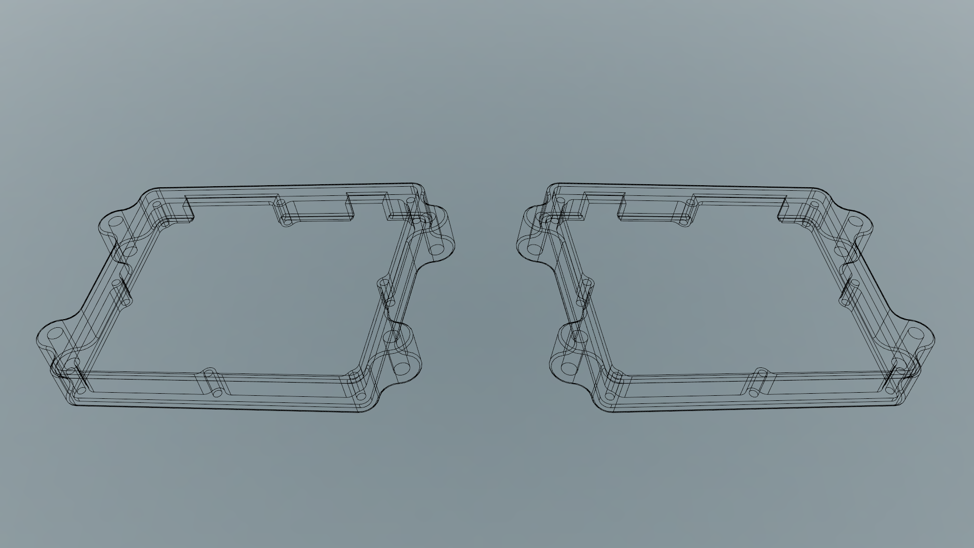
Export the files
The design is done! As a final step, walk through all the dimensions you set and verify that they’re what you expect. Do all the holes align where you expect them to? Are the case dimensions right? Do all the bolts fit? Is there enough space for the PCB to fit?
Once you’re sure about the dimensions, hit the Make button in the Tools tab of the toolbar. Here you can export the STL and optionally directly send it to a slicer of your choice.
Export your models as an STL, or directly send the STL to slicer software you can configure.
As a totally unnecessary but nice to have step, you can adjust the appearance of your model within Fusion by using the appearances menu (A). It looks even better than it did in my sketch!
You can adjust the appearance of your bodies by choosing the materials and colours used.
Print the case
With the file exported, I can now print it. If you don’t have access to a 3D printer, you can send it to a print service like Sculpteo or Shapeways, but keep in mind that the costs for that can be quite high. Alternatively, check out your local makerspace or library, or ask around – people are often happy to help!
Slice the files
I’m printing the files myself, so I’ll need to slice the files myself. For slicing, I use Simplify3D, but other slicers like Cura or Slic3r are perfectly fine and are more affordable alternatives for the same purpose.
Automatic support placement with a resolution of 2,00mm
Retraction: Force retraction between layers, minimum travel for retraction 3,00mm.
The temperature and extrusion multiplier parameters will depend on the filament you use.
The support settings are important! The inner edges for the bottom plate need support, else they will droop and it’ll become a mess, making the print unusable.
A preview of the sliced model in Simplify3D.
I find the settings above made for a relatively quick print at about three and a half hours. Adding an extra perimeter shell adds about twenty minutes but doesn’t make much of a difference.
If you plan to post process the print by sanding and painting it, I recommend adding another outer shell and top and bottom layers, since you’ll remove some material.
Printing and processing
Next up, print the case. Wait for the build plate to cool down a bit after the printer is done, the model will pop off easily. Then carefully remove the supports along the inner bottom edge.
Assemble the keyboard
With the case ready to go, you can assemble the keyboard, as I explained in my Nyquist Build Log. For any case, you’ll probably need to assemble the PCB first, after which you can drop it in and lock it in place with screws.
End result
I’m very pleased with how the case turned out. It’s very sturdy, provides flexibility in tenting and tilting the case, is succesful in hiding the damage of the edges of the plate and it looks quite good to boot!
It took two versions to get a workable case. In the first case the tolerances were too tight, requiring quite a bit of force to get the plate to sit in the case. It’s always a good idea to print parts of the case first to do a test fit, as you can often get away with a very quick print to verify some dimensions.
The Nyquist set up for use. The trackball mouse is a Logitech MX Ergo, using the blue ball from a Logitech M570. The knob in the middle is a 3DConnexion Space Mouse Wireless. Wrist rests are by Fellowes.Right side of the Nyquist.Left side of the Nyquist, showing the cutouts for the connectors. The version shown is an earlier version than the one made in this post, so the connector cutouts aren’t perfectly centered with the jacks.
Further improvements
There are some further improvements I’d want to make:
I could countersink the hex nuts, to make the case sit a bit lower to the desk.
I’d like to experiment with brass heat inserts to provide some inner threads to the tenting bolt holes. That way I might not even need a hex or wing nut to hold the bolt in place.
Someone suggested I use carriage head bolts, that have a flat cap. I could then cover that cap in plastidip or coat it with rubber paint, to provide a lower footprint than the rubber end caps I’m using at the moment.
Use a carriage head bolt dipped in plastidip or coated in rubber, for more grip, lower footprint and less components.
I haven’t used an ortholinear keyboard yet and I wanted to try one. There are many keyboards to choose from. The Nyquist seemed like a good start, since it has plenty of keys with its 5×6 grid, allowing some freedom in mapping the keys where I want them while I figure out a layout I like.
The plates I bought had some damage to it, the drill bit must have drifted off during the assembly. The plates themselves were still usable, though. I was ready to discard the plates and design my own 3D printed plates, but then I thought: What if I design a case in which I can use the plates, hiding the damage?
In another blog post, I explained how to assemble the Nyquist step by step. In this guide, I want to show you how to design the case I used using Autodesk Fusion 360. A case like this makes for a good first project, and I hope I can inspire you to create something like it for yourself!
Decide what features you want
First things first, decide what features you want the case to have. I wanted:
Next to these design goals, there’re also some common sense technical requirements: The PCB, connectors and cables should fit within the case. Custom cables often have thicker plug housings, so we need plenty of space to fit them.
Shopping list
I’m basing my case on the existing Nyquist PCB and plates by keeb.io. I’ll need the following:
To be able to tent the keyboard I want to use four screws per case, and some way to easily fasten them. I bought all these at my local hardware store:
You’ll also need something to measure these parts with. An ordinary ruler will do fine. I got myself 6″ digital calipers from Sparkfun, but any brand will work—my measurements don’t require very high precision.
Designing the case
Now that I have the materials and a general idea of what I want to make, let’s design the case!
I find it helpful to visualize what I want to make. Sometimes it’s enough to just think about it, sometimes I make a sketch.
The sketch above is based on some existing Iris and Nyquist cases I saw, that had four holes along the edge. In them, you can put bolts in order to tent the case. It’s simple and effective, and the materials are relatively cheap and available.
The general idea is: Make a sandwich style case, in which I can countersink the top and bottom plates, fastening them with the included spacers and screws. Then add the nuts and bolts for tenting, and I’m done! Let’s get started with the actual design.
Get the plate files
I’m basing my design off of the existing plates. Thankfully, keeb.io has published case files for the Nyquist on Github, so I can easily import those in my design to get a head start. The file I used was
switch-layer-2u.svgin theexterior-screwsfolder.switch-layer-2u.svg. I modified it to show the lines more clearly here. If you want to design your own, please download the original files from the repository yourself.Insert the SVG into Fusion360
Start by creating a new sketch in Fusion. Then, using the Insert SVG command in the toolbar (under “Insert”), import the downloaded SVG image. For all commands, you can also press
Sand start typing, the command will pop up in a search window.Fusion isn’t able to guess the scale by itself. What I did was import the SVG with the default scale and inspect the two outer edges by pressing
Iand selecting the edges. Fusion will display the distance,94.827mm. Then, I measured the physical width of my plate with my calipers, which turned out to be about126mm.Ias a shortcut).The scale, then, is
126 ÷ 94.827 = 1,328with a bunch more numbers after the comma. Now, delete the inserted SVG and insert a new one, this time using the calculated scale. If you inspect the distance again, you should see that it matches the measurement of the physical plate. If you inspect the distance again, you should see that it matches the measurement of the physical plate.Trace the outlines and screw holes
When importing the SVG, I noticed some curved lines are squiggly. Because I plan to offset the lines, these inconsistencies become bigger, so I make my own straight lines over the squiggly lines.
It’s a good idea to make a new sketch, seperately from the inserted SVG. This way, we can hide the SVG when done, making it easier to select the right sketch profiles later on.
First, add a Center Rectangle somewhere in the middle of the plate, and drag it outwards. It doesn’t have to match up and you don’t have to apply dimensions to it, just double click to get a blue square. Then, using the Colinear constraint, align the edges of the square with the edges of the plate.
Next, match up the outer curves of the case by using the Fillet feature. Play around with the value a bit, I found that 2.25mm matches the case pretty well.
Now add the screw holes. While we don’t need the actual holes, we do need the center points. In my sketch, I wanted the spacers to be contained within the body of the case, so I’ll need to align those with the screw holes on the plates.
I used a similar method to what I used with the tracing of the case outline: making a Center Rectangle and using the a relationship to align it with the edges. Since they’re circles, the Colinear relationship isn’t a good fit: I used the Coincident constraint instead. The intersection of the diagonal lines marks the middle. I then place a point on them onto them, where I can align a circle on top of later.
The dotted lines are so-called Construction Lines. You can toggle this kind of line with the
Xshortcut.The SVG file doesn’t fully match up with the plate I have: according to the file, I should have two holes in the top middle, but my plate only has one. I’ll make a horizontal construction line that’s exactly in the middle, and use the Mirror command to mirror the bottom middle hole to the top.
Sketch the case
With all the important features of the original file traced over, I can start with the case itself. The case is relatively straightforward, so I think I can do most of it in a single sketch, keeping the model uncluttered. I now have three sketches:
Parameters
I make heavy use of the Change Parameters window during this section. I won’t show it every time I add a parameter, so I’ll explain it up front.
You can easily access the Change Parameters window by pressing
Sand typing part of the command name, likeparam.Sand typing part of the command name, likeparam.Parameters help tremendously in reusing dimensions, making it easy to adjust features across the model all at once. If you’d want to change the height of the case, of the diameter of the screws, it’s a breeze with parameters.
Case outlines
I want the plate to be countersunk into the case. That means I’ll need something for the plate to sit on top of, and I’ll need an edge alongside the plate. To do that, I’ll define a few offsets, measured from the edge of the plate:
2.5mmthat will support the plate. Make sure not to make this too wide, otherwise the PCB won’t have enough space. This offset will face inwards.0.8mmthat will be the inner border of the top edge. This will give the plate some wiggle room – also known as tolerance. This offset will face outwards.3.8mmthat will be the outer edge of the case. This is the middle offset plus3mm, meaning the outer edge will become3mmthick. This offset will too face outwards.You can apply an Offset by pressing
Oand selecting the sketch curves you want to offset. In this case, I projected the plate edges from the Nyquist Plate Trace sketch by using the Project command (P) and selecting the plate edges. I then offset them with the Offset command.Spacer holes
Next up are the spacer holes, in which the spacers can reside. I measured the diameter of the spacers and they’re about
3mmwide. Since I’ll be 3D printing this case, I need to account for the tolerances of my printer as well. From experience, I know that my printer adds around0.25mmof material at the edges, making for a total of3mm + (2 × 0.25mm) = 3.5mm. I also add a bit of leeway, making it3.6mmso I’m sure they’ll fit.A good way to go about this is to add a parameter such as
PrinterTolerance, in my case setting it to a safe value of0.3mm. Then, when defining parameters for a hole diameter, add+ (2 * PrinterTolerance), and when adding parameters for sides, add+ PrinterTolerance. This way you’ll have a better chance of the components actually fitting.For each spacer hole, add a Center Diameter Circle (
C). If you click on the point in the middle of one of the squares from an earlier sketch and then drag outwards, it’ll align its center automatically with that of the square. Make sure the other sketch is visible, the lightbulb to the left should be turned on for the Nyquist Plate Trace sketch.Next up, add some body to the spacer holes. It doesn’t need to be very sturdy since the forces don’t act upon it sideways, the body will only need to keep the spacer in place. I took a width of
1,25mmand defined a new parameter:SpacerBodyDiameter = SpacerDiameter + (2 * 1,25). You should end up with something like the following:Tenting screw holes
Now, almost the last part for this sketch, I add the holes in which the tenting screws are placed. I measured the shaft diameter of an M6 bolt, and unsurprisingly it’s about
6mm. With the added printer tolerance, the hole diameter becomes6mm + (2 * PrinterTolerance = 6.6mm.Like the spacer holes, the tenting screw holes will also need a body. They’re thick screws and I like this part to be sturdy, so I pick a body diameter of
2 * TentingBoltHoleDiameter.I want the tenting holes to be spaced uniformly across the edge, so I add a construction line (
X) across the top and the bottom of the case, and define a distance from that line to the center of the hole:TentingBoltHoleDiameter * 2 + 10 mm. This way, if I decide to change the bolt size to something larger, the hole and body will move automatically.It’d be nice if the tenting screw body recessed a bit into the case, so this part of the case won’t sit too far from the body. I used a Tangent constraint to align the edge of the screw body to the inner edge of the case.
You’ll notice I only added the tenting screw holes to one side of the case. We can use the Mirror command to copy them over to the other side. First, draw a construction line across the middle, using a Midpoint constraint on the construction line to the projected (purple) line. This will be added automatically when you hover over the middle before drawing a line—a triangle icon will pop up. Then, select the four circles and use Mirror, selecting the middle construction line as the Mirror Line.
You’ll now end up with this almost complete sketch:
Cutouts for the TRRS and USB jacks
The last part we need to add are the cutouts for the TRRS and USB jacks, so the PCB and cables will fit inside of the case.
Let’s start by measuring the widths and offsets of the protruding parts of the PCB:
11mmwide and is offset11,5mmfrom the side of the PCB.37,6mmwide and is offset10mmfrom the side of the PCB.Now, the PCB should be aligned center with the plate on the X axis, so we can measure the offsets from the middle of the PCB instead. The PCB itself is
110mmwide, putting the center point at55mm. This gives another perspective:11mm + 11,5mm = 32,5mmfrom the side, which puts it at55mm - 22,5mm = 22,5mmfrom the center.37,6mm + 10mm = 47,6mmfrom the side, which puts it at55mm - 47,6mm = 7,4mmfrom the center.Since the exact location of the TRRS jack differs depending on which side you’ve soldered the jack, and because we need a bit of leeway in placing the PCB, I add
3mmof clearance to each side. I ended up with the following final sketch:Extrude the case
With the sketch done, it’s time to make it into something more tangible: a case! With the Extrude command (
E), we can make a body based on a sketch profile. Let’s extrude the case in a couple of steps so it’s easier to see what happens.The middle section
The middle section is the widest part of the body and will support both plates being countersunk on top of it. It encompasses about the entire sketch profile. Be sure to select all parts of the body except for the spacer and tenting screw holes.
I chose to make the middle part as high as the spacers, so the spacers fit within the case.
The top plate countersink
Let’s create an edge along the case, so that the plate can be countersunk into it. After an extrude, the sketch on which it was based will automatically hide, so click on the lightbulb next to the Nyquist case sketch to show it again. Then, hit
Eagain to Extrude, and select the outer edge sketch profiles.You’ll need to rotate the view around to be able to select the sketch profiles this time. One way around this is to disable some selection filters by going to the toolbar, Select → Selection Filters → Deselect all except for Sketch Profiles.
With the outer edge selected, extrude it upwards. You’ll see that the Operation automatically changes to Cut. Be sure to change it back to Join so that you’ll add the outer edge instead of stripping it away.
You can extrude it upwards by the height of the spacers plus some value, for example
4.5mm. The plates are1.5mmtall so there’ll be a nice standing edge which won’t interfere with the keycaps.The bottom plate countersink
The bottom edge looks a lot like the top edge, only it’s shorter to keep the profile slimmer. Take the same steps as when extruding the top plate countersink, only now I’ll choose a negative value for the extrusion so it will extrude downwards. A distance of
-2mmwill be fine and will provide some more room for the plate to fit in.Making space for the jacks
The Extrude command is quite powerful and it allows for many options. In this step, I’ll extrude to both sides of the sketch profile.
First, extrude like normal by pressing
Eand selecting the sketch profiles. Then, in the Extrude window shown right, select Two Sides for the Direction.For the first side, select To Object for the Extent and select the inner ledge as the object. Then, set the Offset to
-2.00mmto keep the ledge intact.For the second side, also select To Object for the Extent and select the bottom edge that was extruded for the bottom plate countersink. Now hit OK and it’s done!
Apply fillets
This is the last step before the file can be exported for printing. The case should be fully functional, but it doesn’t look very nice with the rough edges everywhere. Let’s add some fillets to make it look better and to let it be handled more comfortably.
When 3D printing I found it’s a good idea not to provide too wide fillets to the bottom of the print, since it may cause the print to warp more easily.
Let’s get to work! Let’s do the spacer bodies first. Apply a Fillet by pressing
Fand selecting the edges perpendicular to the spacer holes. You can holdControlto add edges to the selection. Overall, I find a fillet with the same radius as the hole to look good most of the time, so I use the parameterSpacerDiameterI added earlier for the radius.Next, add some fillets to the tenting bolt holes. Again, I use the hole diameter as the fillet radius.
Lastly, I add a
1mmfillet to all the outer edges of the case, including those along the jack cutouts. This makes the case a bit friendlier to handle.Export the files
The design is done! As a final step, walk through all the dimensions you set and verify that they’re what you expect. Do all the holes align where you expect them to? Are the case dimensions right? Do all the bolts fit? Is there enough space for the PCB to fit?
Once you’re sure about the dimensions, hit the Make button in the Tools tab of the toolbar. Here you can export the STL and optionally directly send it to a slicer of your choice.
As a totally unnecessary but nice to have step, you can adjust the appearance of your model within Fusion by using the appearances menu (
A). It looks even better than it did in my sketch!Print the case
With the file exported, I can now print it. If you don’t have access to a 3D printer, you can send it to a print service like Sculpteo or Shapeways, but keep in mind that the costs for that can be quite high. Alternatively, check out your local makerspace or library, or ask around – people are often happy to help!
Slice the files
I’m printing the files myself, so I’ll need to slice the files myself. For slicing, I use Simplify3D, but other slicers like Cura or Slic3r are perfectly fine and are more affordable alternatives for the same purpose.
I used FormFutura Galaxy PLA in the Orion Blue colour.
I used the following settings:
The temperature and extrusion multiplier parameters will depend on the filament you use.
The support settings are important! The inner edges for the bottom plate need support, else they will droop and it’ll become a mess, making the print unusable.
I find the settings above made for a relatively quick print at about three and a half hours. Adding an extra perimeter shell adds about twenty minutes but doesn’t make much of a difference.
If you plan to post process the print by sanding and painting it, I recommend adding another outer shell and top and bottom layers, since you’ll remove some material.
Printing and processing
Next up, print the case. Wait for the build plate to cool down a bit after the printer is done, the model will pop off easily. Then carefully remove the supports along the inner bottom edge.
Assemble the keyboard
With the case ready to go, you can assemble the keyboard, as I explained in my Nyquist Build Log. For any case, you’ll probably need to assemble the PCB first, after which you can drop it in and lock it in place with screws.
End result
I’m very pleased with how the case turned out. It’s very sturdy, provides flexibility in tenting and tilting the case, is succesful in hiding the damage of the edges of the plate and it looks quite good to boot!
It took two versions to get a workable case. In the first case the tolerances were too tight, requiring quite a bit of force to get the plate to sit in the case. It’s always a good idea to print parts of the case first to do a test fit, as you can often get away with a very quick print to verify some dimensions.
Further improvements
There are some further improvements I’d want to make:
Share this post: