Editors note: Since I wrote this article, I’ve started my own keyboard company, splitkb.com. We’ve made our own version of this keyboard, the Aurora Corne. Please check it out!
Earlier this week, my second project arrived: The Corne Keyboard, also known as the Helidox. It’s a small and futuristic looking keyboard designed by Foostan.
I ordered the kit through Mechboards.co.uk, including the OLED screen and RGB LED addons. I also ordered custom split keyboard cables by Pexon. The keycaps were sourced from a secondhand electronic typewriter.
In building this keyboard, I encountered a handful of problems. Because of that, I have made an extensive build log detailing the steps I took and how I solved some of the problems I had.
Table of Contents
Parts
Most parts were contained in the kit from Mechboards. I assumed all parts would be provided, but some parts were not: I missed the reset button and two four-pin headers for the OLED screens. They’re not necessary, but nice to have.
I opted to use Mill-Max Ultra-Low Profile Sockets for the Pro Micro, which I bought from r/mechmarket some time ago. They’re nice, but the holes in the PCB were too tiny for the sockets to fit all the way in, leading to a taller profile than desired.
Costs
Below is a summary of all the parts I ordered. The build can be done cheaper by using standard cables instead of custom made ones and by not using sockets, getting the total to €100. You might also save some more by getting cheaper switches and skipping the OLED screen and LEDs, ultimately getting the price down to about €80.
2 × plate sets, one for each half. Each set consists of a switch plate, OLED/pro micro guard plate and a backplate. The acrylic plates the kit came with are 3mm thick.
2 × Arduino Pro Micro’s. Mine came with the J1 jumpers desoldered.
2 × TRRS jacks.
1 × TRRS cable. The kit came with a TRRS cable, but according to the guide a TRS cable is also supported.
42 × diodes, the kit came with around 50. When using low profile switches, use SMD diodes to save some precious space.
4 × 8mm M2 spacers for the OLED screen/Pro Micro guard plates. If you’re able to trim the height down of the Pro Micro, you might be able to use 6mm spacers.
10 × 6mm M2 spacers. When using low profile switches, you may use 3mm spacers.
28 × M2 screws. The thread of the screws in my kit was 6mm long.
Required but not included
42 × keyswitches, ALPS and Cherry MX compatible (possibly others as well).
42 × keycaps. You need 1u keycaps for most keys, the two innermost thumb keys support 1.5u caps.
Optional parts
2 × Reset buttons. Nice to have, you’re able to manually short the pins, or once assembled you may assign the RESET keycode to a button on the keyboard itself.
10 × Cushion rubber pieces. You can get these at any hardware store. I used TESA Protect 8mm rubber which I had lying around.
1 or 2 × SSD1306 OLED modules. Optionally included in the kit.
1 or 2 × 4-pin headers for the OLED modules. These came preinstalled on the OLED modules in the kit.
1 or 2 × 4-pin sockets for the OLED modules. Handy for socketing them so you won’t need to desolder them if something goes wrong.
54 × SK6812MINI RGB LEDs. 42 are used upward mounted for backlight, 12 are used mounted downward for underglow. Optionally included in the kit.
2 × WS2812 Serial LED Tape, six LED’s each. You can use this as a possibly cheaper alternative to the SK6812MINI LEDs. They’re not meant to be used together, so either use the SMD LEDs, or use the LED tape.
Build steps
A Corne Keyboard PCB, the starting point for the build.
The PCB is (mostly) mirrored, except for the part where the Pro Micro’s and the OLED screen mount. Choose which half you will use for which side.
You may snap off the outer column if you decide you won’t use those keys, which makes for an even tinier keyboard. Keep in mind you’ll then also need an other case. You might be able to edit the case files if you do.
Diodes
Once the plate with switches is installed, there’s no way to get under the plate again without desoldering all the switches first. It’s a good idea to install all components on the underside, with a few exceptions:
When using an RGB strip, it can be a good idea to mount the diodes on the front side so you’ll get a lower profile. There should be enough space at the front side to install both diodes and switches, check for it to be sure.
When using low profile switches, you must use SMD diodes, and you must install them on the back side, otherwise the switch plate won’t fit.
Bending the diodes using a lead forming tool.
Start by bending the diodes. You can use a tool, or bend them using the edge of a backplate.
Pay attention to the direction of the diodes. The black line should face the line on top of the triangle.
Pay attention when installing the diodes: they only work in one direction! Desoldering them is a pain, so check their orientation before soldering.
Bending the legs help the diodes stay in place while soldering.
If you plan to use sockets for installing the Pro Micro’s, you might want to save the legs you cut off of the diodes, since normal headers might not fit in the sockets. Diode legs are quite slim, fitting in most sockets.
Save the clipped off diode legs when you want to mount components into sockets.All diodes installed!
LEDs (optional)
You may use either a LED strip for underglow, or SMD LEDs for both backlighting and underglow. I have chosen for the SMD LEDs.
Soldering the SMD LEDs is doable, but you need to be precise and take caution:
Use a low temperature when soldering the LEDs! You may burn them out, and this happens quickly. I set my soldering iron to 300 degrees Celcius (572 degrees Fahrenheit). See the comments on this thread on Reddit.
Don’t make contact for too long with the LEDs! You may burn them out, even with a lower temperature. As a general guideline, if making a connection won’t work in the first five seconds, move on to another LED and let it cool off for a bit. You don’t need to wait too long as it cools quickly, but it’s good to be careful.
The orientation of the LEDs matters! You may take a look at the SK6812MINI datasheet. See the photo’s below for a closeup and do take a good look at the build guide as well. The orientation is different for underglow and backlighting LEDs, and it’s different for the top three underglow LEDs compared to the bottom three, too!
Apply flux to the contact points, across the PCB to the LED.
Apply a small blob of soldering tin to the soldering iron.
In a steady stroke, apply the tin from the soldering iron to both contact points in a smooth motion.
Repeat the above three steps for every contact point.
I did it in another way. I didn’t use flux, and heated the PCB pad first for about five seconds, applied tin, then moved the soldering iron over to the LED, applied heat for about four seconds while applying a tiny blob of tin. I often had to revisit a pad in order to get the tin applied correctly, but as long as you don’t heat the pads too much, it’s alright. Either way works, just take care!
Pay special attention to the direction of the LEDs. An aid: the largest pad should always be the nearest to the circle on the PCB.
When placing the LEDs, it’s a good idea to use a pair of tweezers. If you carefully drop the LED in place, it’ll stay in place. Dropping the LEDs into the holes takes some practise, as they’ll easily fall through.
Installed LEDs. Note the underglow LEDs, facing forward in this picture. An aid: The dark patch should always face away from the circle on the PCB.
When troubleshooting the LEDs, it’s a good idea to look at the diagram in the build guide. Each LED is in the order noted below. Often, all LEDs up to a certain point in the order work fine, and the others may not turn on or may turn on in unexpected colours. When that happens, take a look at the first LED in the sequence that doesn’t work. You may need to redo the solder joints or you may need to replace it when you have a burned out or otherwise faulty LED.
You may skip this step when not using an OLED screen.
I believe it doesn’t hurt to add them in the event you want to use them sometime in the future, though. You’ll need to desolder the Pro Micro to get to the jumpers later if you don’t perform this step now.
OLED jumpers. They’re located below the Pro Micro, so be sure to solder them first before installing the Pro Micro.
While the LEDs were installed on the back side of the PCB, you’ll need to solder the jumpers on the front side, where you’ll also want to have the switches. The pads don’t seem to be connected from the front to the back, so which side you choose does matter.
Soldered jumpers. Shiny!
TRRS jacks
I used some isolation tape to hold the jack in place while soldering. It’s a good idea to solder one point first so you’ll be able to adjust the alignment easily.
Keep in mind that the component gets quite hot to the touch when in contact with the soldering iron for a longer time. It shouldn’t hurt the component, but it may hurt your fingers.
Keeping the TRRS jack in place while soldering with some electrical isolation tape.
Reset switches (optional)
If you were wise enough to order some reset switches, this is a good time to install them. I wasn’t and so I don’t have a picture of a reset switch for you here.
OLED screen sockets (optional)
If you have 4-pin sockets for the OLED screens, you may install them now. They’re not required, but can be handy for maintenance and aesthetics.
Pro Micro
It’s a good idea to flash firmware to both Pro Micro’s first, so that you’ll know you don’t have a defective unit before soldering them to the board.
I used the command make crkbd:default and flashed the firmware using the QMK Toolbox.
Sockets for the Pro Micro. Installing sockets is entirely optional and should make a replacement easier.
The Pro Micro may take up quite a bit of height. The kit supplied both 6mm and 8mm spacers for the OLED screens. Because of the sockets I installed, 10mm spacers would’ve been better. The original build guide provides for some ways to make the Pro Micro require less height.
Installed pro micro
OLED screen (optional)
You may need to install the 4-pin headers onto the OLED screen modules first. The ones in my kit came preinstalled.
If you installed 4-pin sockets, you can simply insert the OLED screen into place. If you did not, you can solder the OLED screen directly to the board like I did.
The OLED screen and acrylic plate installed. It’s starting to look like something now!
Check operation
Before moving on with the final steps, it’s a good idea to check the operation of the board.
The default build of the firmware writes some debugging information onto the OLED screen. Short each switch footprint with a pair of tweezers or some hookup wire, and note the output on the display. Each switch should correspond with its own spot in the keyboard matrix, for example 3x5 for row 3 × column 5.
Assert that each LED is working, both front and back.
Generally, if all LEDs are lit, you’ve installed everything fine.
I had soldered a connection badly on one of the underglow LEDs, LED number 4 wasn’t installed correctly in my case. Since the LEDs are installed in series, all LEDs after the fourth one didn’t work. This makes it easy to pinpoint where the fault is.
On the other half, I likely broke one of the LEDs, causing the data passed from that broken LED to the others to be corrupt. This gave a nice disco-like effect, every time I’d change the colour, each LED was assigned a seemingly random colour. Replacing the LED solved this issue.
Key switches and top plate
With all of the internal components working, it’s time for the final steps.
The switch plate, to be mounted on the front.
Prepare the switch plate by removing any protective film and attaching the spacers to it.
Then press the switches into the plate. You don’t need to use much force. Pay attention to the alignment of the switches, they should match the switch footprints on the PCB.
Adding the switches to the switch plate.
Now place the switch plate onto the PCB, aligning the switch pins and spacers to their respective footprints. You’re now ready to solder the switches into place.
Before soldering each switch, check if it’s still inserted fully into the plate. The switches are held in place by friction, and it’s easily to push them out of place slightly during soldering, leaving the switch slanted.
After you’re done soldering the switches, do a visual check: check if each switch is inserted fully into the plate. If it isn’t, desolder the switch and then solder it again. It’s easier to correct this now, though the back plate is easily detached.
All switches soldered into place on the right half.
Back plate
You can add some rubber bumpers to the bottom of the case so it won’t slide around on your desk, and to protect the acrylic from scratches. I added six bumpers per back plate for stability.
Screw the back plate into place, into the five spacers that are attached to the switch plate. You can use a single screwdriver for this. If you use two, take care not to over-tighten the screws, since the acrylic plate may crack this way.
The back plate screwed into place.
Keycaps
You can add any keycap that’s compatible with the switches you’ve chosen. You’ll need 42 keycaps. You may use all 1u keycaps, or use wider 1.5u keycaps for the innermost thumb keys.
Cleaned keycaps from a used electronical typewriter.
I opted to harvest the caps from a second hand typewriter for this build, a Triumph Adler Gabriele 7007L.
Firmware
You may want to customize the firmware for the board. You can follow the Complete Newbs Guide from the official QMK documentation to get your development environment up and running. It also includes steps on how to customize your first firmware.
Conclusion
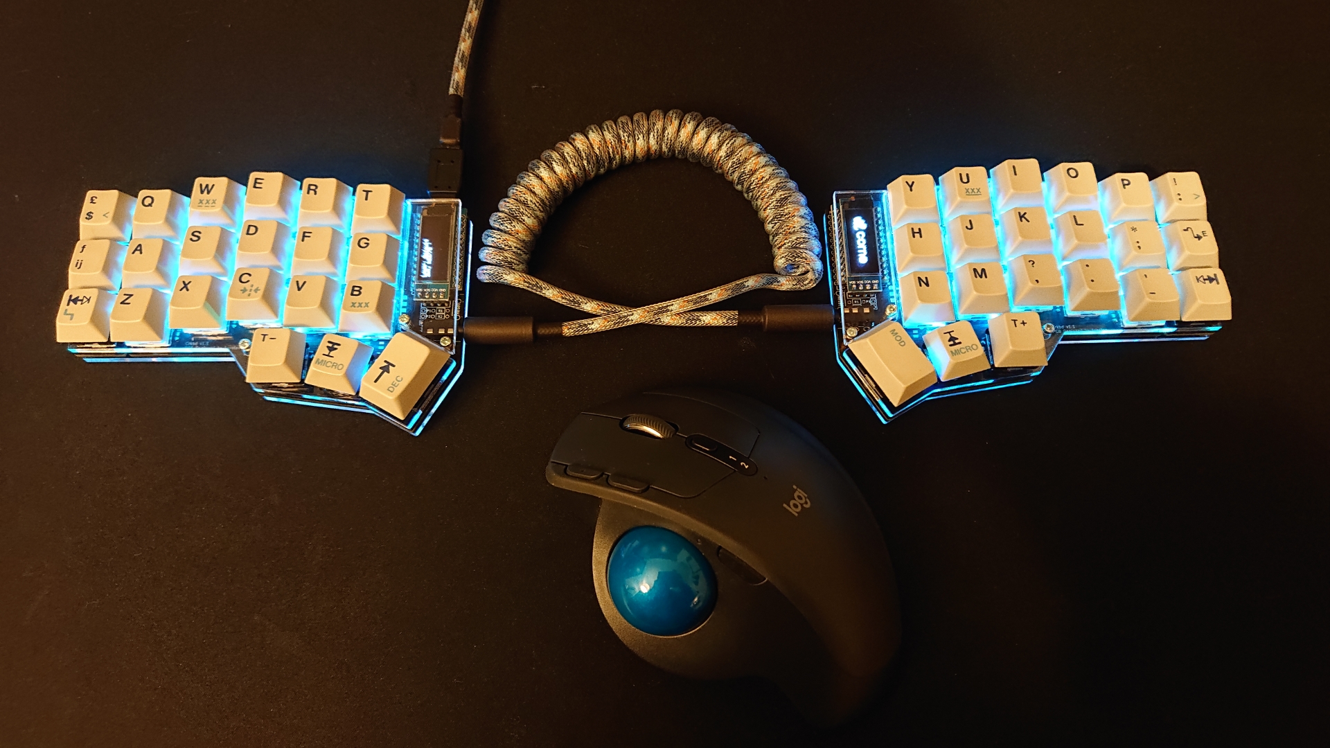
The end result: A Corne keyboard with typewriter caps. The mouse pictured is a Logitech MX Ergo, using the trackball from a Logitech M570 trackball mouse.
I’m very happy with how this build turned out. It looks like it came right out of the box, with the acrylic, lighting and overall polished look.
The left half displays some keylogging info by default, handy for debugging during the build.The right half displays the Corne logo. It can be customized using your keymap.
Discussion
There are some things I’ll definitely do again for the next build, and there are some lessons learned.
Taking a lot of care when soldering the LEDs took quite some time and patience. I’d say it paid off, having broken only one LED. There are some extras in the kit, I had five LEDs unused at the end, so I had some leeway there.
Assembling one half before doing the other half was a good idea. It allowed me to make pictures during the first half. I then wrote the build log, noted which pictures I was missing, and added those during the assembly of the second half. If you don’t want to write a build log, I would just assemble it both sides at once, though: it does take more time this way.
Next time, I should carefully read the build log and parts lists before starting. I opted to skip the reset button and OLED screen pin headers during this build. They’re not required, but had I known that in advance I’d have ordered those parts before starting out.
This was my first time using sockets for the Pro Micro. Soldering thinner headers on them took quite some time, a bit more than an hour for both units. I’m sure it’ll be a good investment if I were to accidentally break a Pro Micro. I should do more research about suitable headers. Using the sockets I did caused the Pro Micro to require more height than I wanted, leading to a slanted OLED screen guard.
Compared to my first build, the keeb.io Iris, this keyboard looks a lot more finished. This is mainly because of the keycaps, case and lighting. If I am to build another Iris, I’ll for sure invest more into a better case, perhaps one laser cut from sheet metal.
Overall I’m really happy. I learned quite a bit, especially about soldering SMD components, and I’m looking forward to using this board. Thanks for reading. If you have any questions, feel welcome to join our Discord server!
Editors note: Since I wrote this article, I’ve started my own keyboard company, splitkb.com. We’ve made our own version of this keyboard, the Aurora Corne. Please check it out!
Earlier this week, my second project arrived: The Corne Keyboard, also known as the Helidox. It’s a small and futuristic looking keyboard designed by Foostan.
I ordered the kit through Mechboards.co.uk, including the OLED screen and RGB LED addons. I also ordered custom split keyboard cables by Pexon. The keycaps were sourced from a secondhand electronic typewriter.
There are build guides available: the original guide by Foostan (in Japanese), and an English translation by Durnlaw and Skyvsaur. The guides are fairly complete. You may also be interested in the source files of the PCB and case.
In building this keyboard, I encountered a handful of problems. Because of that, I have made an extensive build log detailing the steps I took and how I solved some of the problems I had.
Table of Contents
Parts
Most parts were contained in the kit from Mechboards. I assumed all parts would be provided, but some parts were not: I missed the reset button and two four-pin headers for the OLED screens. They’re not necessary, but nice to have.
I opted to use Mill-Max Ultra-Low Profile Sockets for the Pro Micro, which I bought from r/mechmarket some time ago. They’re nice, but the holes in the PCB were too tiny for the sockets to fit all the way in, leading to a taller profile than desired.
Costs
Below is a summary of all the parts I ordered. The build can be done cheaper by using standard cables instead of custom made ones and by not using sockets, getting the total to €100. You might also save some more by getting cheaper switches and skipping the OLED screen and LEDs, ultimately getting the price down to about €80.
Required and included in the kit
Required but not included
Optional parts
RESETkeycode to a button on the keyboard itself.Build steps
The PCB is (mostly) mirrored, except for the part where the Pro Micro’s and the OLED screen mount. Choose which half you will use for which side.
You may snap off the outer column if you decide you won’t use those keys, which makes for an even tinier keyboard. Keep in mind you’ll then also need an other case. You might be able to edit the case files if you do.
Diodes
Once the plate with switches is installed, there’s no way to get under the plate again without desoldering all the switches first. It’s a good idea to install all components on the underside, with a few exceptions:
Start by bending the diodes. You can use a tool, or bend them using the edge of a backplate.
Pay attention when installing the diodes: they only work in one direction! Desoldering them is a pain, so check their orientation before soldering.
If you plan to use sockets for installing the Pro Micro’s, you might want to save the legs you cut off of the diodes, since normal headers might not fit in the sockets. Diode legs are quite slim, fitting in most sockets.
LEDs (optional)
You may use either a LED strip for underglow, or SMD LEDs for both backlighting and underglow. I have chosen for the SMD LEDs.
Soldering the SMD LEDs is doable, but you need to be precise and take caution:
I found a very helpful video on how to solder the LEDs made by Foostan after I completed the build. In it, he shows how he solders the LEDs:
I did it in another way. I didn’t use flux, and heated the PCB pad first for about five seconds, applied tin, then moved the soldering iron over to the LED, applied heat for about four seconds while applying a tiny blob of tin. I often had to revisit a pad in order to get the tin applied correctly, but as long as you don’t heat the pads too much, it’s alright. Either way works, just take care!
When placing the LEDs, it’s a good idea to use a pair of tweezers. If you carefully drop the LED in place, it’ll stay in place. Dropping the LEDs into the holes takes some practise, as they’ll easily fall through.
When troubleshooting the LEDs, it’s a good idea to look at the diagram in the build guide. Each LED is in the order noted below. Often, all LEDs up to a certain point in the order work fine, and the others may not turn on or may turn on in unexpected colours. When that happens, take a look at the first LED in the sequence that doesn’t work. You may need to redo the solder joints or you may need to replace it when you have a burned out or otherwise faulty LED.
OLED screen jumpers (optional)
You may skip this step when not using an OLED screen.
I believe it doesn’t hurt to add them in the event you want to use them sometime in the future, though. You’ll need to desolder the Pro Micro to get to the jumpers later if you don’t perform this step now.
While the LEDs were installed on the back side of the PCB, you’ll need to solder the jumpers on the front side, where you’ll also want to have the switches. The pads don’t seem to be connected from the front to the back, so which side you choose does matter.
TRRS jacks
I used some isolation tape to hold the jack in place while soldering. It’s a good idea to solder one point first so you’ll be able to adjust the alignment easily.
Keep in mind that the component gets quite hot to the touch when in contact with the soldering iron for a longer time. It shouldn’t hurt the component, but it may hurt your fingers.
Reset switches (optional)
If you were wise enough to order some reset switches, this is a good time to install them. I wasn’t and so I don’t have a picture of a reset switch for you here.
OLED screen sockets (optional)
If you have 4-pin sockets for the OLED screens, you may install them now. They’re not required, but can be handy for maintenance and aesthetics.
Pro Micro
It’s a good idea to flash firmware to both Pro Micro’s first, so that you’ll know you don’t have a defective unit before soldering them to the board.
I used the command
make crkbd:defaultand flashed the firmware using the QMK Toolbox.The Pro Micro may take up quite a bit of height. The kit supplied both 6mm and 8mm spacers for the OLED screens. Because of the sockets I installed, 10mm spacers would’ve been better. The original build guide provides for some ways to make the Pro Micro require less height.
OLED screen (optional)
You may need to install the 4-pin headers onto the OLED screen modules first. The ones in my kit came preinstalled.
If you installed 4-pin sockets, you can simply insert the OLED screen into place. If you did not, you can solder the OLED screen directly to the board like I did.
Check operation
Before moving on with the final steps, it’s a good idea to check the operation of the board.
The default build of the firmware writes some debugging information onto the OLED screen. Short each switch footprint with a pair of tweezers or some hookup wire, and note the output on the display. Each switch should correspond with its own spot in the keyboard matrix, for example
3x5for row 3 × column 5.Generally, if all LEDs are lit, you’ve installed everything fine.
I had soldered a connection badly on one of the underglow LEDs, LED number 4 wasn’t installed correctly in my case. Since the LEDs are installed in series, all LEDs after the fourth one didn’t work. This makes it easy to pinpoint where the fault is.
On the other half, I likely broke one of the LEDs, causing the data passed from that broken LED to the others to be corrupt. This gave a nice disco-like effect, every time I’d change the colour, each LED was assigned a seemingly random colour. Replacing the LED solved this issue.
Key switches and top plate
With all of the internal components working, it’s time for the final steps.
Prepare the switch plate by removing any protective film and attaching the spacers to it.
Then press the switches into the plate. You don’t need to use much force. Pay attention to the alignment of the switches, they should match the switch footprints on the PCB.
Now place the switch plate onto the PCB, aligning the switch pins and spacers to their respective footprints. You’re now ready to solder the switches into place.
Before soldering each switch, check if it’s still inserted fully into the plate. The switches are held in place by friction, and it’s easily to push them out of place slightly during soldering, leaving the switch slanted.
After you’re done soldering the switches, do a visual check: check if each switch is inserted fully into the plate. If it isn’t, desolder the switch and then solder it again. It’s easier to correct this now, though the back plate is easily detached.
Back plate
You can add some rubber bumpers to the bottom of the case so it won’t slide around on your desk, and to protect the acrylic from scratches. I added six bumpers per back plate for stability.
Screw the back plate into place, into the five spacers that are attached to the switch plate. You can use a single screwdriver for this. If you use two, take care not to over-tighten the screws, since the acrylic plate may crack this way.
Keycaps
You can add any keycap that’s compatible with the switches you’ve chosen. You’ll need 42 keycaps. You may use all 1u keycaps, or use wider 1.5u keycaps for the innermost thumb keys.
I opted to harvest the caps from a second hand typewriter for this build, a Triumph Adler Gabriele 7007L.
Firmware
You may want to customize the firmware for the board. You can follow the Complete Newbs Guide from the official QMK documentation to get your development environment up and running. It also includes steps on how to customize your first firmware.
Conclusion
I’m very happy with how this build turned out. It looks like it came right out of the box, with the acrylic, lighting and overall polished look.
Discussion
There are some things I’ll definitely do again for the next build, and there are some lessons learned.
Taking a lot of care when soldering the LEDs took quite some time and patience. I’d say it paid off, having broken only one LED. There are some extras in the kit, I had five LEDs unused at the end, so I had some leeway there.
Assembling one half before doing the other half was a good idea. It allowed me to make pictures during the first half. I then wrote the build log, noted which pictures I was missing, and added those during the assembly of the second half. If you don’t want to write a build log, I would just assemble it both sides at once, though: it does take more time this way.
Next time, I should carefully read the build log and parts lists before starting. I opted to skip the reset button and OLED screen pin headers during this build. They’re not required, but had I known that in advance I’d have ordered those parts before starting out.
This was my first time using sockets for the Pro Micro. Soldering thinner headers on them took quite some time, a bit more than an hour for both units. I’m sure it’ll be a good investment if I were to accidentally break a Pro Micro. I should do more research about suitable headers. Using the sockets I did caused the Pro Micro to require more height than I wanted, leading to a slanted OLED screen guard.
Compared to my first build, the keeb.io Iris, this keyboard looks a lot more finished. This is mainly because of the keycaps, case and lighting. If I am to build another Iris, I’ll for sure invest more into a better case, perhaps one laser cut from sheet metal.
Overall I’m really happy. I learned quite a bit, especially about soldering SMD components, and I’m looking forward to using this board. Thanks for reading. If you have any questions, feel welcome to join our Discord server!
Share this post: