I’ve recently finished building my first custom mechanical keyboard, the Keeb.io Iris. This post goes into detail about the decisions I made, the problems I encountered and the steps I took during the build.
I’ve been typing on mechanical keyboards since a few years. I really couldn’t go back to typing on typical rubber dome keyboards. In 2015 I started using a Keyed Up Labs ES-87 with Cherry MX Brown switches at work. Two years later I also wanted a board for home use and went with the Novatouch TKL, which at the time was a very affordable and readily available board with Topre switches.
I frequent the mechanical keyboards subreddit where I often see posts about split keyboards. I grew interested in them and eventually I caved in and bought an Ergodox EZ. It’s a real piece of engineering with many features and an intuitive online configurator.
I found that I wasn’t using nearly as many keys as the Ergodox provides. Searching for split keyboards with less keys than the Ergodox yielded many results, though almost all of them were hand-built.
I thought it’d be a nice achievement to build my own keyboard. And using the QMK framework I can adapt it precisely to my needs.
Why I’m building an Iris
I hadn’t soldered much before this project. My only experience was many years ago in some classes at school. I was looking for a project that wasn’t necessarily easy but was accessible for beginners like me. With the Iris being mainly a through-hole soldering project, it fit those criteria.
The Iris provides less keys than the Ergodox, which was exactly what I’m looking for. It’s availability through proxies is nice, costing me less in import and shipping.
There are other alternatives like the Corne keyboard, the ErgoTravel and the Minidox. They weren’t as easily available in Europe. I did find the Corne keyboard available at MechBoards after I ordered the Iris parts, and I ordered those too on a whim.
Supplied parts
I ordered an Iris kit (revision 2.5) from CandyKeys. The kit provides most of the parts needed for building an Iris. I received the following:
2 PCBs. The layout is mirrored, so either side can be used for left or right.
2 TRRS jacks, used for connecting the two parts together.
2 reset switches.
56 diodes. I believe I was supplied with sixty, so I had some to spare when I desoldered one and it broke.
2 4.7k ohm resistors for I2C communication. They’re not necessary, but easily installed and provide for more options in the future.
Other necessary parts
The kit doesn’t provide all necessary parts. You’re able to customize it to your heart’s content. These are components you’re able to choose:
Two Arduino Pro Micro’s. I bought them from a Dutch webstore, TinyTronics. You can buy cheaper clones from Chinese webshops as AliExpress or DX, and there are also alternatives listed below.
One TRRS cable. It looks like a standard 3.5mm cable but with four rings instead of three. I bought a custom made cable from Pexon. The shipping can take a long time, about four weeks in my case, but I think it’s worth it because their quality is excellent.
One Micro USB cable. I also ordered this from Pexon. You can use any Micro USB cable you’ve got lying around, as long as it supports both power and data.
54 to 56 Alps or MX-compatible switches. I went with a variety of switches: 40 heavy Hako True switches, 8 Cherry MX Brown switches and 8 Cherry MX Speed Silver switches. They can be difficult to source, I bought them at CandyKeys and at Reichelt. More about why I picked these switches below.
If you want to add LEDs for backlighting and underglow, there are a few more parts you will need in order to complete the keyboard:
The LED support kit. It contains two MOSFETs for converting the voltage to a higher level and two resistors. It’s necessary to drive the LEDs because the board itself can’t provide a high enough voltage for them.
54 to 56 LEDs for backlight if you want them. Which ones fit will depend on your switches, refer to the frequently asked questions for some more information.
54 to 56 470 ohm resistors for the LEDs.
WS2812B compatible LED strips for underglow. I ordered some from AliExpress. The product page on keeb.io recommends to use 12 to 14 LEDs for the Iris.
I opted to add most of these parts later. I did buy and install the parts that weren’t possible to install once the build is finished, in case I would want LEDs after the build anyway.
Build log
With most components received, it was time to start assembling the boards!
As a side note: Most components go on the bottom of the keyboard. Once you solder in the switches there’s no way to go back to the top part of the board unless you desolder all the switches. When something breaks, you’ll be glad to have soldered all components to the bottom.
I set my soldering iron to a temperature of 260 degrees Celcius (500 degrees Fahrenheit). Perhaps I could’ve gone higher, but I was afraid of causing damage to the board.
Diodes
Diodes, held in place by bending the legs. This makes it easier to solder them to the PCB. Keep attention to the direction when placing them!
Bending the legs makes it easier to solder the diodes to the board. Take care when placing them as they need to be installed in a particular direction. I didn’t take care soldering the very first one and desoldering it was a pain, eventually breaking the diode due to impatience. Thankfully I was supplied with about 60 diodes, so I had a few to spare.
LED support components
Placing the resistors using the same technique as with the diodes. The direction doesn’t matter for diodes.
I wasn’t sure whether I would want LEDs yet. Since installing components is easier when the switches are not yet soldered to the board, I opted to install them in case I wanted LEDs later – they’re easy to turn off in any case.
I hadn’t received the LED support kit yet. I read on reddit that it’s possible to install MOSFETs later. Since the board is mirrored and the pads interconnect, it shouldn’t matter on which side you solder them.
Reset buttons and TRRS jacks
Overview of the Iris PCB so far, with resistors, diodes, the TRRS jacks and reset buttons. You can see I’ve also placed the two resistors to allow for I2C communication, to the left of the left TRRS jack.
Soldering the jacks and buttons is easy at this point. I held them together to the board with electrical tape while soldering them.
A tip for soldering most components: it’s easier to adjust the orientation of components by soldering only one point, and keeping that point hot while rotating the component around.
I2C resistors
The build guide advises to install components for I2C in order to accomodate for future extensions, like a numpad or OLED screen. I thought the idea of having an OLED screen was neat, since the Corne keyboard also has it. At this point, it’s not much of a hassle to install two extra resistors, so on they go.
Pro Micro header pins
A pair of headers soldered to the board, to allow for the installation of a Pro Micro.
I’ve read about the Micro USB port failing on the Arduino Pro Micro’s. The ports are very fragile since they are surface-mount soldered to the board instead of through-hole. I’ve applied some instant glue to the sides of the ports for reinforcement. So far they’ve held up fine, though I do take caution when removing the cable.
I ordered some sockets so I could insert and remove Pro Micro easily from the keyboard. Shipping them took long however and impatience got the best of me: I ended up soldering them directly to the PCB anyway.
LEDs
Using tape to hold the LEDs in place.
The build guide advises to perform this step after installing the switches. Since I opted to use box switches instead of conventional Cherry-style switches for most keys, I had to solder many of the LEDs before I soldered the switches. Following the guide, the LEDs are inserted through the switches, but box switches slide on top of the LEDs making inserting them afterwards impossible.
The LEDs I ordered proved to be a bit too long for the box switches I had. I first tried to manually sand a millimeter or two off of them. Thanks to a tip from a friend, I tried trimming them with a dremel, making for an easier job.
Don’t hold the LEDs with your fingers if you ever find you need to trim LEDs. Using pliers keeps your fingers safe and keeps the LED steady, providing a more reliable result.
Trimming a few millimetres off of the LEDs was an easy job for a dremel with a sanding bit.
The LEDs were also too large for the profile of a Cherry MX switch. I still need to order LEDs for those keys, but I think I want to see the rest of the LEDs working first — installing them later should be easy.
Switches
Installing the corners first to make sure the rest of the switches will be aligned. You can also see the LEDs well here.
Installing the switches was easy. I needed to bend the LEDs a bit inward to make room for the box switches, since they were quite close to the edges of the plate.
I tested each switch before soldering. I imagine desoldering switches to be more of a pain than the diode I had to desolder earlier. Most multimeters have a continuity test mode, meaning they provide a beep when a circuit connects. In my case, holding a probe to each pin of the switch and pressing it provided a beep, making testing the switches quick and easy.
Place and solder the switches in the corners first in order to make sure the plate is aligned correctly. Then install the rest of the switches – I put them in place one by one and soldered all of them in one go after. Placing the switches might require some force: it’s a good idea to start at one edge and work your way to the other edge, it gets easier as you go.
All the switches installed for the left half.
I’ve chosen to use a few different kinds of switches.
Hako True switches
Hako True switches are used for all alphanumeric keys. They’re relatively easy to actuate (register the key as being pressed) and then require an increasing amount of force to bottom out (press them in all the way). They’re also slightly tactile, meaning they provide a small but noticeable bump when pressed, providing feedback that the keypress did register.
This should encourage me to only press the keys slightly, making less noise and requiring less travel.
I also use Cherry MX Brown switches on my work keyboard and I like them very much. For the Iris, I’ve chosen to use them for often used keys that require a press instead of holding them like space, enter and escape. Cherry MX Brown switches are tactile, providing a noticeable bump when pressed.
Speed silver switches are linear, meaning they don’t provide a bump like the other two kinds of switches I’ve used. These switches require a very low force required to actuate and hold them, making them ideal to use for modifier keys.
A Pro Micro, the heart of the keyboard. Each half has its own Pro Micro, one acting as the master which receives keypresses from the slave, and transmits them to the computer. Scale in centimeters.
There’s a helpful guide available over at the QMK documentation. Following that will get you a local build environment, allowing you to build and flash firmware for the Iris and many other QMK-supported keyboards.
The very first thing you should do is flash the Pro Micros in order to make sure they work. Setting up your environment and building your first firmware can take about half an hour. Do this before you solder the Pro Micros, since desoldering can take a lot of time.
Before soldering the Pro Micro’s, check if you have a J1 jumper to the left of the Micro USB port. Pro Micro clones usually won’t have this, but if you do, only the side plugged into the computer will work as per the keeb.io troubleshooting guide. My Pro Micro’s did have the jumper and I only read the troubleshooting guide later, which cost me a few hours to figure out.
Pay attention to the orientation when soldering the Pro Micros! I carelessly didn’t read this step in the guide and thankfully did solder the first board the right way, but I might not have been so lucky.
A tip: there are alternatives to the Pro Micro that have a less fragile USB port and that provide some other extras. Two of those alternatives are the Elite-C controller by keeb.io and the QMK Proton C board. The Elite-C is not readily available in Europe, and the QMK Proton C board is still in group-buy status at the time of writing. Because of those reasons I went with the Pro Micro.
Installing the caps
I finished one half first since I was eager to test it.
The last thing to do is to add the caps onto the board. I have to say that I like these cheap caps, though it’d be nice if the profile matched the rows better. It’s hard to find compatible caps for an ortholinear keyboard since this used mostly the smaller 1u keycaps, while keys like shift are often larger than that.
End result
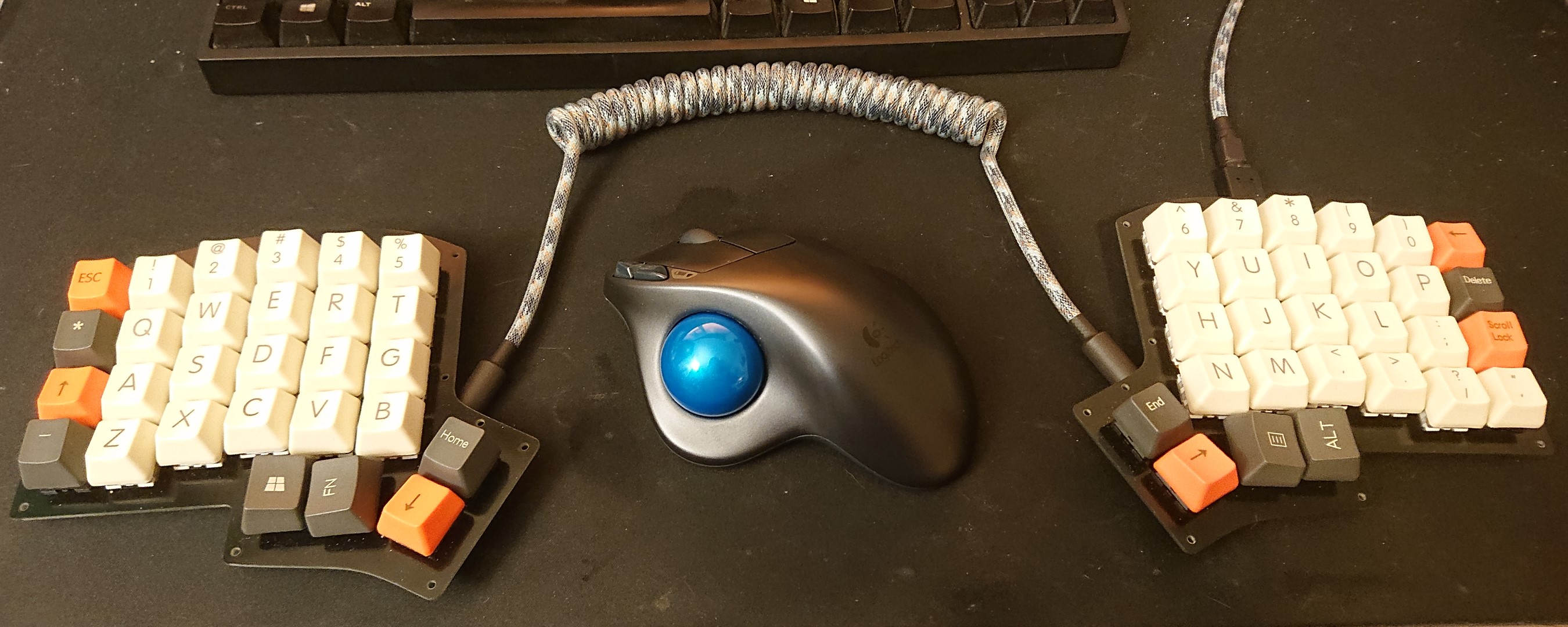
The (almost) finished Iris keyboard and a Logitech M570 trackball mouse.
I’m still missing a few parts, the most important of which are the spacers between the plate and the underside of the case. I also have some LED strips and MOSFETs in shipping to finish the backlight and underglow.
Other than that, the keyboard works like a charm!
Conclusion
I’m glad with the way it turned out, especially since this was my first project. It cost me about twelve hours, including the time spent to customize the firmware.
The Iris is a very suitable project for beginners to hard- and software. Some computer literacy helps in figuring out the firmware side of the keyboard: building and customizing it is described quite accurately in the documentation, but if you don’t know what a terminal or command prompt is you may need to spend a few more hours fiddling around to get it working.
Discussion
Next time, I should probably wait for more components to arrive before soldering. The Pro Micro headers arrived a day after I soldered the headers onto the board. A little patience might’ve saved me from potentially having to replace a Pro Micro the hard way.
It is a good idea to read all available documentation before getting started: the official build guide, the troubleshooting page and the frequently asked questions. It would’ve saved me some headaches, especially with the J1 jumper I should’ve desoldered before it became a problem.
I want to take more pictures of the build process next time and spend some more time to make them look better.
I went with a PCB-plate because it was readily available, but I think I would’ve liked an aluminium or acrylic case better. I want to spend some more attention to that side of the build next time because the plate is very hard to replace once all the switches are soldered.
Thanks for reading the guide! If you have any questions, you can find me on Reddit.
I’ve recently finished building my first custom mechanical keyboard, the Keeb.io Iris. This post goes into detail about the decisions I made, the problems I encountered and the steps I took during the build.
Are you building an Iris yourself? Do refer to the official build guide and take a quick look at the troubleshooting and frequently asked questions pages on keeb.io before continuing.
Table of Contents
Why I’m building a custom mechanical keyboard
I’ve been typing on mechanical keyboards since a few years. I really couldn’t go back to typing on typical rubber dome keyboards. In 2015 I started using a Keyed Up Labs ES-87 with Cherry MX Brown switches at work. Two years later I also wanted a board for home use and went with the Novatouch TKL, which at the time was a very affordable and readily available board with Topre switches.
I frequent the mechanical keyboards subreddit where I often see posts about split keyboards. I grew interested in them and eventually I caved in and bought an Ergodox EZ. It’s a real piece of engineering with many features and an intuitive online configurator.
I found that I wasn’t using nearly as many keys as the Ergodox provides. Searching for split keyboards with less keys than the Ergodox yielded many results, though almost all of them were hand-built.
I thought it’d be a nice achievement to build my own keyboard. And using the QMK framework I can adapt it precisely to my needs.
Why I’m building an Iris
I hadn’t soldered much before this project. My only experience was many years ago in some classes at school. I was looking for a project that wasn’t necessarily easy but was accessible for beginners like me. With the Iris being mainly a through-hole soldering project, it fit those criteria.
The Iris provides less keys than the Ergodox, which was exactly what I’m looking for. It’s availability through proxies is nice, costing me less in import and shipping.
There are other alternatives like the Corne keyboard, the ErgoTravel and the Minidox. They weren’t as easily available in Europe. I did find the Corne keyboard available at MechBoards after I ordered the Iris parts, and I ordered those too on a whim.
Supplied parts
I ordered an Iris kit (revision 2.5) from CandyKeys. The kit provides most of the parts needed for building an Iris. I received the following:
Other necessary parts
The kit doesn’t provide all necessary parts. You’re able to customize it to your heart’s content. These are components you’re able to choose:
Light it up!
If you want to add LEDs for backlighting and underglow, there are a few more parts you will need in order to complete the keyboard:
I opted to add most of these parts later. I did buy and install the parts that weren’t possible to install once the build is finished, in case I would want LEDs after the build anyway.
Build log
With most components received, it was time to start assembling the boards!
As a side note: Most components go on the bottom of the keyboard. Once you solder in the switches there’s no way to go back to the top part of the board unless you desolder all the switches. When something breaks, you’ll be glad to have soldered all components to the bottom.
I set my soldering iron to a temperature of 260 degrees Celcius (500 degrees Fahrenheit). Perhaps I could’ve gone higher, but I was afraid of causing damage to the board.
Diodes
Bending the legs makes it easier to solder the diodes to the board. Take care when placing them as they need to be installed in a particular direction. I didn’t take care soldering the very first one and desoldering it was a pain, eventually breaking the diode due to impatience. Thankfully I was supplied with about 60 diodes, so I had a few to spare.
LED support components
I wasn’t sure whether I would want LEDs yet. Since installing components is easier when the switches are not yet soldered to the board, I opted to install them in case I wanted LEDs later – they’re easy to turn off in any case.
I hadn’t received the LED support kit yet. I read on reddit that it’s possible to install MOSFETs later. Since the board is mirrored and the pads interconnect, it shouldn’t matter on which side you solder them.
Reset buttons and TRRS jacks
Soldering the jacks and buttons is easy at this point. I held them together to the board with electrical tape while soldering them.
A tip for soldering most components: it’s easier to adjust the orientation of components by soldering only one point, and keeping that point hot while rotating the component around.
I2C resistors
The build guide advises to install components for I2C in order to accomodate for future extensions, like a numpad or OLED screen. I thought the idea of having an OLED screen was neat, since the Corne keyboard also has it. At this point, it’s not much of a hassle to install two extra resistors, so on they go.
Pro Micro header pins
I’ve read about the Micro USB port failing on the Arduino Pro Micro’s. The ports are very fragile since they are surface-mount soldered to the board instead of through-hole. I’ve applied some instant glue to the sides of the ports for reinforcement. So far they’ve held up fine, though I do take caution when removing the cable.
I ordered some sockets so I could insert and remove Pro Micro easily from the keyboard. Shipping them took long however and impatience got the best of me: I ended up soldering them directly to the PCB anyway.
LEDs
The build guide advises to perform this step after installing the switches. Since I opted to use box switches instead of conventional Cherry-style switches for most keys, I had to solder many of the LEDs before I soldered the switches. Following the guide, the LEDs are inserted through the switches, but box switches slide on top of the LEDs making inserting them afterwards impossible.
The LEDs I ordered proved to be a bit too long for the box switches I had. I first tried to manually sand a millimeter or two off of them. Thanks to a tip from a friend, I tried trimming them with a dremel, making for an easier job.
Don’t hold the LEDs with your fingers if you ever find you need to trim LEDs. Using pliers keeps your fingers safe and keeps the LED steady, providing a more reliable result.
The LEDs were also too large for the profile of a Cherry MX switch. I still need to order LEDs for those keys, but I think I want to see the rest of the LEDs working first — installing them later should be easy.
Switches
Installing the switches was easy. I needed to bend the LEDs a bit inward to make room for the box switches, since they were quite close to the edges of the plate.
I tested each switch before soldering. I imagine desoldering switches to be more of a pain than the diode I had to desolder earlier. Most multimeters have a continuity test mode, meaning they provide a beep when a circuit connects. In my case, holding a probe to each pin of the switch and pressing it provided a beep, making testing the switches quick and easy.
Place and solder the switches in the corners first in order to make sure the plate is aligned correctly. Then install the rest of the switches – I put them in place one by one and soldered all of them in one go after. Placing the switches might require some force: it’s a good idea to start at one edge and work your way to the other edge, it gets easier as you go.
I’ve chosen to use a few different kinds of switches.
Hako True switches
Hako True switches are used for all alphanumeric keys. They’re relatively easy to actuate (register the key as being pressed) and then require an increasing amount of force to bottom out (press them in all the way). They’re also slightly tactile, meaning they provide a small but noticeable bump when pressed, providing feedback that the keypress did register.
This should encourage me to only press the keys slightly, making less noise and requiring less travel.
Cherry MX Brown switches
I also use Cherry MX Brown switches on my work keyboard and I like them very much. For the Iris, I’ve chosen to use them for often used keys that require a press instead of holding them like space, enter and escape. Cherry MX Brown switches are tactile, providing a noticeable bump when pressed.
Cherry MX Speed Silver switches
Speed silver switches are linear, meaning they don’t provide a bump like the other two kinds of switches I’ve used. These switches require a very low force required to actuate and hold them, making them ideal to use for modifier keys.
Pro Micros
There’s a helpful guide available over at the QMK documentation. Following that will get you a local build environment, allowing you to build and flash firmware for the Iris and many other QMK-supported keyboards.
The very first thing you should do is flash the Pro Micros in order to make sure they work. Setting up your environment and building your first firmware can take about half an hour. Do this before you solder the Pro Micros, since desoldering can take a lot of time.
Before soldering the Pro Micro’s, check if you have a J1 jumper to the left of the Micro USB port. Pro Micro clones usually won’t have this, but if you do, only the side plugged into the computer will work as per the keeb.io troubleshooting guide. My Pro Micro’s did have the jumper and I only read the troubleshooting guide later, which cost me a few hours to figure out.
Pay attention to the orientation when soldering the Pro Micros! I carelessly didn’t read this step in the guide and thankfully did solder the first board the right way, but I might not have been so lucky.
A tip: there are alternatives to the Pro Micro that have a less fragile USB port and that provide some other extras. Two of those alternatives are the Elite-C controller by keeb.io and the QMK Proton C board. The Elite-C is not readily available in Europe, and the QMK Proton C board is still in group-buy status at the time of writing. Because of those reasons I went with the Pro Micro.
Installing the caps
The last thing to do is to add the caps onto the board. I have to say that I like these cheap caps, though it’d be nice if the profile matched the rows better. It’s hard to find compatible caps for an ortholinear keyboard since this used mostly the smaller 1u keycaps, while keys like shift are often larger than that.
End result
I’m still missing a few parts, the most important of which are the spacers between the plate and the underside of the case. I also have some LED strips and MOSFETs in shipping to finish the backlight and underglow.
Other than that, the keyboard works like a charm!
Conclusion
I’m glad with the way it turned out, especially since this was my first project. It cost me about twelve hours, including the time spent to customize the firmware.
The Iris is a very suitable project for beginners to hard- and software. Some computer literacy helps in figuring out the firmware side of the keyboard: building and customizing it is described quite accurately in the documentation, but if you don’t know what a terminal or command prompt is you may need to spend a few more hours fiddling around to get it working.
Discussion
Next time, I should probably wait for more components to arrive before soldering. The Pro Micro headers arrived a day after I soldered the headers onto the board. A little patience might’ve saved me from potentially having to replace a Pro Micro the hard way.
It is a good idea to read all available documentation before getting started: the official build guide, the troubleshooting page and the frequently asked questions. It would’ve saved me some headaches, especially with the J1 jumper I should’ve desoldered before it became a problem.
I want to take more pictures of the build process next time and spend some more time to make them look better.
I went with a PCB-plate because it was readily available, but I think I would’ve liked an aluminium or acrylic case better. I want to spend some more attention to that side of the build next time because the plate is very hard to replace once all the switches are soldered.
Thanks for reading the guide! If you have any questions, you can find me on Reddit.
Share this post: