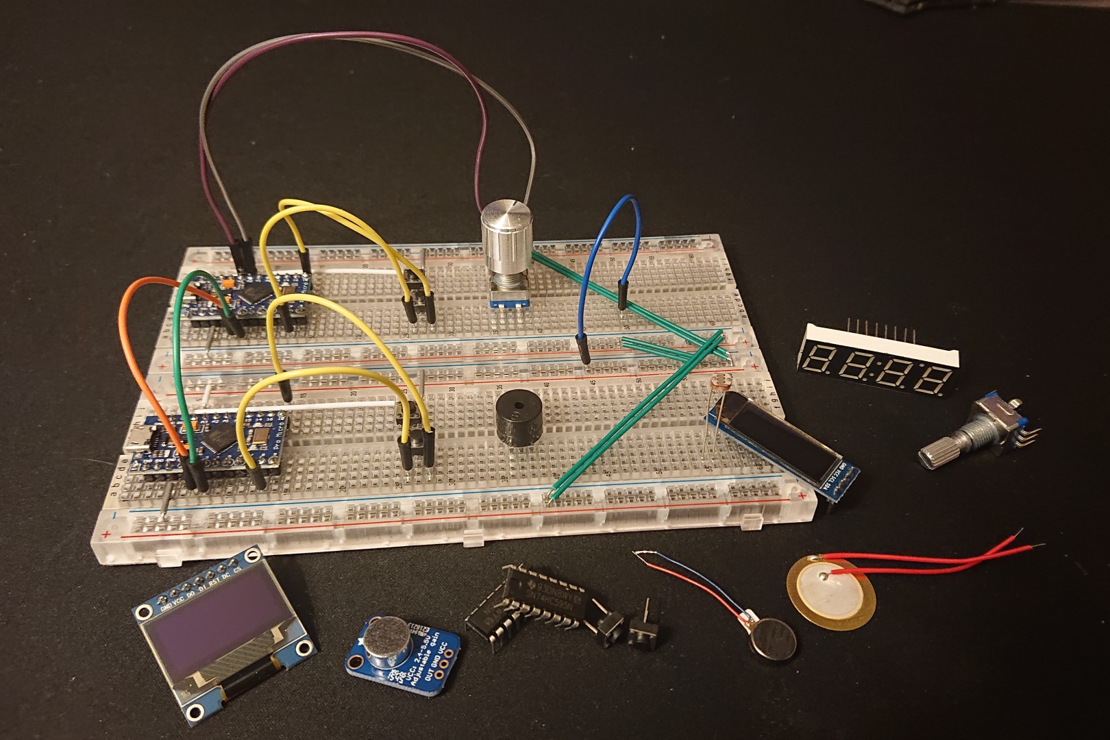
I’ve built an Iris keyboard last week. It uses two Pro Micro controllers for communication between the pair of keyboards and the computer. This article mainly applies to revisions 2 to 2.5 of the Iris keyboard.
I’m researching whether I can do modifications to the board, such as adding an OLED screen or using a rotary encoder. In order to do that, I’ll need some free pins on the microcontroller.
Pinout diagram
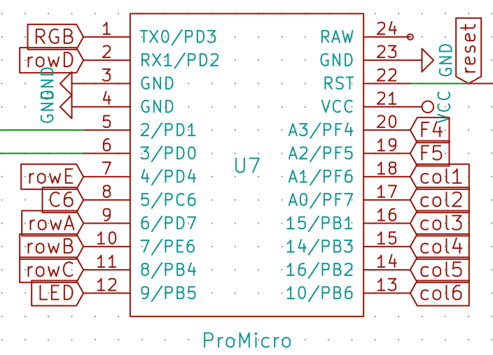
Copyright © 2018 Hexwire, LLC
I found the above diagram in the documentation from Keeb.io. Most pins have a label, but two of them don’t. I set out to see whether all those pins see use, so I can use some of the pins for my own modifications.
Available pins
I posted a question on the olkb subreddit (short for Ortholinear keyboard). The owner of keeb.io, bakingpy and QMK collaborator drashna were kind enough to provide some answers, and with their answers I was also able to find some unused pins in the firmware. In summary:
- The pins
D0andD1are used for I2C communication and serial. They’re wired to the TRRS jack and connect to the Pro Micro on the other side of the Iris. - The
C6pin is used for audio whenAUDIO_ENABLEis set in therules.mkfile. You might be able to reuse this pin, but only if you don’t use audio or put audio on another pin. - The
F4pin is unused in the rev2 version of the Iris. It is used in rev1_led and rev3, however, as a column pin. - The
F5pin is unused in the rev2 version of the Iris. It is used as a column pin in rev3. - The
B0andD5pins are used for the LEDs on the Pro Micro. They are not broken out on the PCB of the Pro Micro, and thus are also not broken out on the Iris itself. Theoretically, you might desolder the LEDs and reassign the pins in order to gain more space.
Pin mapping in firmware
The use of these pins is defined somewhere. The Iris makes use of the QMK software project as its firmware. Every keyboard is able to define configuration, mapping pins of the microcontroller to various functions of the keyboard.
I wanted to know exactly what pins get used for what, so I made a table with all broken out pins on the Pro Micro and their purpose for rev2 of the Iris, ordered by location on the PCB. Note: other revisions for the Iris do use other pins for some functionality, but you’ll be able to look at the source files to see those configurations.
The files for the Iris are located in the QMK firmware repository, under keyboards/iris. Not all pins are defined there: some are assigned by convention.
| Pin | Use | Source |
| D3 | RGB | config.h, defined as RGB_DI_PIN |
| D2 | rowD | config.h, used in MATRIX_ROW_PINS |
| D1 | SDA | Used for serial/I2C. |
| D0 | SCL | Used for serial/I2C. |
| D4 | rowE | config.h, used in MATRIX_ROW_PINS |
| C6 | C6 | audio.c, used when C6_AUDIO is defined when the firmware is built. |
| D7 | rowA | config.h, used in MATRIX_ROW_PINS |
| E6 | rowB | config.h, used in MATRIX_ROW_PINS |
| B4 | rowC | config.h, used in MATRIX_ROW_PINS |
| B5 | LED | config.h, defined as BACKLIGHT_PIN |
| B6 | col6 | config.h, used in MATRIX_COL_PINS |
| B2 | col5 | config.h, used in MATRIX_COL_PINS |
| B3 | col4 | config.h, used in MATRIX_COL_PINS |
| B1 | col3 | config.h, used in MATRIX_COL_PINS |
| F7 | col2 | config.h, used in MATRIX_COL_PINS |
| F6 | col1 | config.h, used in MATRIX_COL_PINS |
| F5 | F5 | Not used in revision 2. |
| F4 | F4 | Not used in revision 2. |
I haven’t yet found direct references to the D0 and D1 pins that are used for serial or I2C communication. They’re not defined in Iris-specific code, at any rate.
Digging deeper, I could find other references to these pins:
- In
drivers/avr/pro_micro.h, the ports are defined indigital_pin_to_port_PGM. - In the same folder, there is the file
i2c_master.h, which looks interesting. It includesavr/io.h, which in turn includesiom32u4.h, an IO file specific to the microcontroller used in the Pro Micro, the ATmega32U4. It assigns various ports to defines. I’m sure those defines get used in other core code related to serial and I2C communication, but that was a bit outside of the scope of this article.
Conclusion
After receiving help and digging through the QMK and AVR code, the following ports are available on an Iris keyboard when using a Pro Micro:
F4F5B0andD5if you’re willing to desolder the LEDs on the Pro Micro, soldering wire to those connection points and remapping the pins in the firmware.
Discussion
It might be possible to hook up a SPI or I2C port expander on the D0 and D1 pins, making the available ports less of an issue.
Interaction with I2C devices may be possible on the D0 and D1 pins, though the Iris uses serial by default. Switching the protocol to I2C should be possible according to the keeb.io FAQ (last question) and the Iris build guide. If you followed the optional step to solder I2C resistors, hardware support should already be there.
Software support for I2C doesn’t exist specifically for the Iris. There are split boards that do use I2C, such as the Corne keyboard (also known as the Helidox).
With the use cases I have, adding an OLED display and a rotary encoder, I also looked up related documentation and cases.
There exists support for SSD1306 based OLED displays in QMK, based on I2C communication. This requires changed to the protocol listed above.
Reddit user /u/LurkerMcNoPost has made a post of his Iris that succesfully uses a rotary encoder, with links to code he wrote to make it work. Official QMK support for encoders also exists, and doesn’t seem to need a specific protocol or ports. For this, the F4 and F5 ports could be used.
0 comments on “What extra pins can I use on the Iris keyboard from keeb.io?”